
Introduction to Meyers E-47 and E-60 Electrical Systems
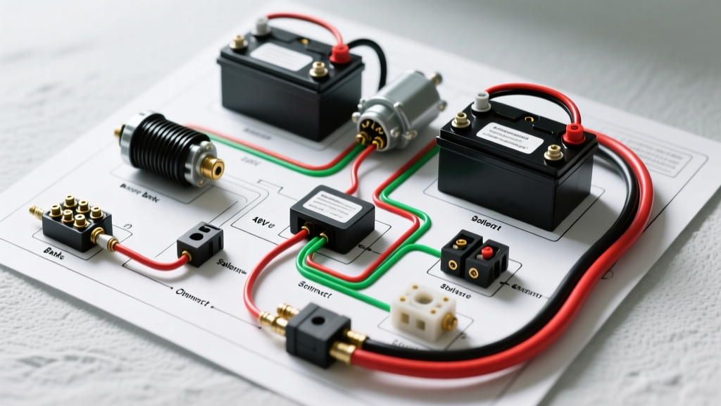
Wiring a Meyers snow plow—specifically the ubiquitous E-47 and E-60 hydraulic models—requires a meticulous approach to high-amperage DC circuits and low-voltage signal routing. While modern multiplex systems are becoming common, the vast majority of DIY installations and fleet retrofits in 2026 still rely on the proven Meyers 13-pin analog relay harness. A flawed wiring diagram interpretation or undersized wire gauge will result in catastrophic voltage drops, welded solenoid contacts, or backfed signals that can destroy a modern truck's Body Control Module (BCM).
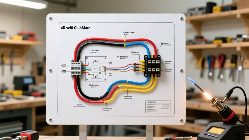
This step-by-step wiring walkthrough provides the exact specifications, pinout matrices, and routing protocols required to safely integrate a Meyers plow harness into your host vehicle. We will bypass generic advice and focus on the precise mechanical and electrical tolerances demanded by high-load hydraulic motors.
Required Materials and Exact Specifications
Before cutting a single wire, verify your materials against these professional-grade specifications. Using standard automotive wire from a big-box store will lead to premature insulation cracking in sub-zero temperatures.
- Main Power Wire: 10 AWG or 8 AWG SAE J1128 cross-linked polyethylene (XLPE) stranded copper. (Cost: ~$0.85/ft).
- Control/Signal Wire: 16 AWG or 18 AWG GXL primary wire for cab-to-harness routing.
- Solenoid: 40A Continuous Duty Solenoid (e.g., Trombetta 974-1215-010 or White-Rodgers 586-902). Do not use a standard intermittent Bosch-style relay. (Cost: $45 - $65).
- Terminals: 3/8-inch ring terminals with 3:1 adhesive-lined heat shrink. Standard vinyl crimp caps will fail under hood vibration.
- Crimping Tool: Ratcheting crimper calibrated for 10-8 AWG non-insulated terminals (e.g., Titan 11100 or Klein 3005CR).
- Connector Kit: Meyers 13-pin vehicle-side and plow-side mating connectors with silicone weather seals.
Meyers 13-Pin Connector Pinout Matrix
The Meyers 13-pin connector is the industry workhorse for analog plow systems. Below is the standard pinout configuration. Always verify your specific harness manual, as custom fleet orders may repurpose auxiliary pins.
| Pin Number | Wire Color | Circuit Function | Load / Amperage |
|---|---|---|---|
| 1 | White | Main System Ground | High (Return path) |
| 2 | Brown | Marker / Clearance Lights | < 5A |
| 3 | Yellow | Left Turn / Stop Signal | < 10A |
| 4 | Green | Right Turn / Stop Signal | < 10A |
| 5 | Black/Red | Plow Headlights (Low/High) | 15A - 20A |
| 6 | Blue | Solenoid Trigger (Cab Switch) | < 2A |
| 7 | Red | 12V Battery Feed (Main Power) | 150A - 250A (Peak) |
| 8 | Purple | Auxiliary / Spare Circuit | Varies |
| 9 | Orange | Headlight Isolation Trigger | < 1A |
| 10 | Pink | Daytime Running Light (DRL) Override | < 2A |
| 11 | Gray | Spare / Future Expansion | N/A |
| 12 | Light Green | Backup Lights | < 5A |
| 13 | Black | Secondary Ground / Shield | Low |
Phase 1: Vehicle-Side Harness Routing and Relay Setup
Step 1: Main Power and Ground Isolation
Route the 10 AWG red main power wire from the truck's battery positive terminal to the firewall. Critical Rule: Maintain a minimum clearance of 6 inches from any exhaust manifolds or turbocharger downpipes. Install a 150A mega-fuse within 8 inches of the battery terminal to protect the entire harness in the event of a dead short.
For the main ground (Pin 1), do not rely on the engine block or alternator bracket. Run a dedicated 10 AWG or 8 AWG ground wire directly from the battery negative terminal to the vehicle-side 13-pin connector. Sand the mounting surface to bare metal, apply a zinc-rich anti-corrosion compound, and secure with a stainless steel bolt and star washer.
Step 2: Headlight Isolation Module Integration
Modern trucks use pulse-width modulation (PWM) or CAN-bus signals for headlight control. Tapping directly into the OEM headlight wires to trigger the plow lights will cause BCM faults or flickering. Install the Meyers headlight isolation module behind the grille. Cut the OEM headlight feeds and splice the isolation module inline. This ensures the plow's high-draw halogen or LED arrays draw power directly from the plow harness (Pin 5), while the truck's OEM wiring only carries the low-amp trigger signal (Pin 9).
Phase 2: Plow-Side Motor and Solenoid Termination
Step 3: The Continuous Duty Solenoid Mandate
The most common DIY failure in Meyers E-47/E-60 wiring is the use of a standard 40A automotive relay (often mistakenly called a solenoid) to trigger the hydraulic pump motor. A standard relay is rated for intermittent duty (typically 2-3 minutes). A snow plow motor drawing 180 amps under heavy hydraulic load will melt the internal contacts of an intermittent relay, welding them shut and causing the pump to run until the battery dies or the wiring catches fire.
Expert Directive: You must use a continuous-duty solenoid rated for at least 80A continuous / 250A inrush. Mount the solenoid on the plow frame, not the truck, to minimize the length of the high-amperage un-fused wire crossing the A-frame hinge.
Step 4: Motor Grounding Protocol
The hydraulic motor casing is painted or powder-coated, which acts as an electrical insulator. Relying on the motor mounting bolts for a ground path will result in severe voltage drop and sluggish plow performance. Strip a 1-inch section of insulation from a 10 AWG black wire, crimp on a 3/8-inch ring terminal, and bolt it directly to the motor's dedicated ground stud or a scraped section of the motor end-cap. Route this wire back to Pin 1 on the plow-side connector.
Critical Failure Modes and Diagnostic Matrix
When your Meyers plow fails to respond, use this diagnostic matrix to isolate the electrical fault before replacing expensive hydraulic components.
| Symptom | Probable Electrical Cause | Diagnostic & Repair Protocol |
|---|---|---|
| Solenoid clicks rapidly, motor does not turn | Severe voltage drop on the main ground circuit or corroded 13-pin ground pins. | Measure voltage drop across the ground circuit under load. If > 0.2V, clean pins with contact cleaner and re-crimp the battery ground ring terminal. |
| Motor runs, but plow moves sluggishly | Undersized power wire or failing continuous-duty solenoid internal contacts. | Check voltage at the motor stud while angling the plow. If voltage drops below 10.5V, replace the solenoid and inspect wire for internal strand corrosion. |
| Truck headlights dim or flicker when plow is raised | Headlight isolation module failure or backfeed into the truck's PWM lighting circuit. | Verify the isolation module trigger wire (Pin 9) is not spliced into a CAN-bus line. Ensure the module's main power feed is independent. |
| Pump runs continuously after releasing the cab switch | Solenoid contacts welded shut due to using an intermittent-duty relay. | Disconnect the main battery immediately. Replace with a Trombetta or White-Rodgers continuous-duty solenoid. Never use a standard 5-pin Bosch relay. |
Final Testing and Weatherproofing
Once all terminations are complete, apply a generous coating of dielectric grease to the interior pins of both the vehicle-side and plow-side 13-pin connectors. Do not use silicone RTV sealant on the pins, as it will prevent proper electrical mating and trap moisture inside the connector housing. Instead, use dielectric grease to displace moisture and prevent galvanic corrosion between the brass pins.
Perform a functional load test: angle the plow fully left, fully right, and raise it completely while monitoring the truck's dashboard voltmeter. The voltage should not dip below 12.2V at idle. If it does, verify your alternator output and ensure the main power wire is routed to the alternator's main output stud rather than a distant fuse block.
Industry Standards and Safety References
All wire gauge selections, routing clearances, and termination methods outlined in this guide comply with current automotive and electrical safety standards. For further reading on primary cable specifications and heavy-duty relay mandates, consult the following authoritative resources:
- SAE International Automotive Standards - Specifically SAE J1128 for low-tension primary cable insulation requirements in extreme temperature environments.
- Buyers Products Technical Information - The parent company of Meyers snow plows, providing OEM wiring schematics, torque specs, and hydraulic flow charts for E-47 and E-60 units.
- NFPA Codes and Standards - Reference for general DC overcurrent protection and mega-fuse placement protocols to prevent thermal runaway in high-amperage mobile equipment.