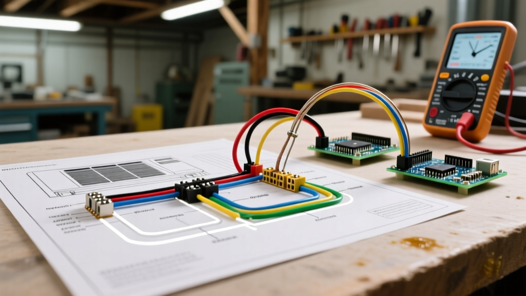

The Anatomy of an Air Conditioner Electrical Wiring Diagram
Understanding an air conditioner electrical wiring diagram is the difference between a swift, accurate repair and hours of frustrating trial-and-error. Modern HVAC systems, particularly those meeting the stringent 2026 SEER2 efficiency standards, rely on complex interactions between high-voltage power delivery and low-voltage control logic. Whether you are troubleshooting a legacy 14-SEER split system or a cutting-edge variable-speed inverter setup, the wiring diagram is your master blueprint. According to the U.S. Department of Energy, improper electrical diagnostics account for a significant percentage of premature compressor failures, making diagram literacy a critical skill for any technician or advanced DIYer.
Ladder Diagrams vs. Pictorial Diagrams
Manufacturers typically provide two types of schematics inside the condenser access panel:
- Pictorial Diagrams: These illustrate the physical layout of the components. They show you exactly where the contactor, capacitor, and compressor are located and how the wires route between them. They are excellent for physical wire tracing but poor for understanding electrical logic.
- Ladder Diagrams: These strip away the physical layout and display the circuit as a logical flowchart. Power sources are on the vertical rails (L1 and L2), and loads/switches are on the horizontal rungs. Ladder diagrams are essential for diagnosing control board logic and safety interlock failures.
High-Voltage vs. Low-Voltage Circuits
An air conditioner electrical wiring diagram is fundamentally divided into two distinct zones: the line voltage (high-voltage) circuit and the control (low-voltage) circuit. Mixing these up can instantly destroy a control board or create a severe shock hazard.
Standard Low-Voltage Thermostat Wire Color Codes
The low-voltage side operates at 24VAC, stepped down by a transformer in the indoor air handler. While manufacturers sometimes deviate, the industry standard 18 AWG thermostat wire color code is nearly universal. Reference this table when tracing Y1, G, and C circuits:
| Terminal | Standard Color | Function | Voltage State (Calling for Cool) |
|---|---|---|---|
| R / Rc | Red | 24VAC Hot (Power) | 24VAC Constant |
| C | Blue / Black | 24VAC Common | 0V (Return Path) |
| Y / Y1 | Yellow | Compressor Contactor Coil | 24VAC when engaged |
| G | Green | Indoor Blower Fan Relay | 24VAC when engaged |
| W / W1 | White | Heat Call (Furnace/Heat Strip) | 0V (Cooling Mode) |
| O / B | Orange | Reversing Valve (Heat Pumps) | 24VAC (O) or 0V (B) depending on brand |
Tracing the 240V Compressor Circuit
The high-voltage side of the diagram details the path of 240V single-phase power from the main service panel to the outdoor condenser. This circuit is governed by NEC Article 440, which dictates that branch circuit conductors must be sized at 125% of the largest motor rated-load current plus the sum of other loads.
When reading the diagram, trace the 240V path through these critical nodes:
- Disconnect Box: Power enters a fused or non-fused pull-out disconnect (e.g., Square D DPU223RB). The diagram will show L1 and L2 entering the box.
- Contactor: The 240V passes through the heavy-duty contacts of the contactor (commonly a Mars 21001 30A model). The diagram shows the coil symbol (often a circle or rectangle) on the low-voltage rung, but the physical contacts on the high-voltage line.
- Dual Run Capacitor: Once the contactor pulls in, 240V reaches the capacitor. The diagram will label the terminals as C (Common), HERM (Hermetic Compressor), and FAN. The capacitor provides the necessary phase shift to generate starting torque.
- Compressor Terminals: Power finally reaches the compressor's three glass-to-metal seal terminals: C (Common), S (Start), and R (Run).
CRITICAL SAFETY WARNING: A dual run capacitor (e.g., 45/5 MFD 440V) can retain a lethal electrical charge long after the disconnect is pulled. Before touching any wiring referenced in the high-voltage diagram, bridge the capacitor terminals with a 20,000-ohm, 5-watt resistor to safely bleed the stored energy. Never use a standard screwdriver to short the terminals, as this can weld the tool to the capacitor and cause an arc flash.
Decoding the Indoor Air Handler Wiring
The indoor air handler diagram focuses heavily on the control board, the 24V transformer, and the blower motor circuit. The transformer (typically rated at 40VA) steps down 120V/240V to 24VAC. If the diagram shows a 3A fuse on the secondary side of the transformer, this is a critical diagnostic point; a blown 3A fuse almost always indicates a short in the low-voltage thermostat wire or a grounded contactor coil outside.
PSC vs. ECM Blower Motor Wiring Differences
As of 2026, the vast majority of new air handlers utilize Electronically Commutated Motors (ECM) rather than legacy Permanent Split Capacitor (PSC) motors. The wiring diagrams for these two technologies are vastly different:
- PSC Motors: The diagram will show multiple color-coded wires (Black, Blue, Red, White) tapping into different winding speeds on the control board relays. Voltage is applied directly to the windings.
- ECM Motors (e.g., Genteq X13): The diagram will show a constant 120V/240V high-voltage feed to the motor module, plus a low-voltage communication harness (usually 4 or 5 pins). The control board sends low-voltage signals to tell the internal microprocessor what RPM to target. You cannot test an ECM motor with a standard multimeter continuity check; you must use a specialized TEC motor tester.
Common Wiring Diagram Faults & Diagnostic Steps
When a system fails to cool, use the wiring diagram to isolate the failure point. According to OSHA electrical safety guidelines, always verify the absence of voltage with a CAT III or CAT IV rated multimeter (like the Fluke 116 HVAC multimeter, approx. $220) before touching conductors.
Step-by-Step Contactor Coil Diagnosis
If the outdoor fan and compressor are dead, but the indoor blower is running, follow this sequence using your diagram:
- Verify 24V at the Condenser: Set your multimeter to AC Voltage. Measure between the Y1 and C wires at the outdoor terminal block. You should read 24VAC. If you read 0V, the fault is indoors (broken wire, blown fuse, or open safety switch like a float switch).
- Check the Coil Continuity: Turn off the high-voltage disconnect. Remove the Y1 and C wires from the contactor coil. Set your meter to Ohms. Measure across the coil terminals. A healthy 24V coil (like on a Honeywell R8228A1018) will read between 15 and 25 ohms. If it reads 'OL' (Open Line), the coil is burnt out and the contactor must be replaced.
- Check for Mechanical Binding: If the coil reads correctly and receives 24V, but the contactor won't pull in, the mechanical armature may be stuck due to pitting or insect debris. Do not force it; replace the contactor.
Frequently Asked Questions
Why does my wiring diagram show a 'Low Pressure Switch' in series with the contactor coil?
This is a safety interlock. The diagram shows the 24V Y1 signal passing through the normally-closed (NC) low-pressure switch before reaching the contactor. If the system loses its refrigerant charge, the switch opens, breaking the 24V circuit to prevent the compressor from running without adequate cooling return gas, which would destroy the compressor windings.
Can I use 14 AWG wire for a 30A condenser circuit if the run is very short?
No. Even if the physical distance is short, NEC Article 440 and the unit's data plate dictate the Minimum Circuit Ampacity (MCA). If the MCA is 19.5A, you must use a minimum of 12 AWG copper wire. Always size the wire to the MCA and the breaker to the Maximum Overcurrent Protection (MOCP) listed on the manufacturer's data plate, regardless of the diagram's simplified line drawings.
What does the 'DEF' or 'DF' terminal on a heat pump diagram mean?
This refers to the Defrost cycle. In heat pump wiring diagrams, the defrost board will temporarily energize the reversing valve (to switch to cooling mode) and the auxiliary heat strips simultaneously to melt ice off the outdoor coil without blowing cold air into the living space.