
Decoding the Standard Kenwood 16-Pin Harness
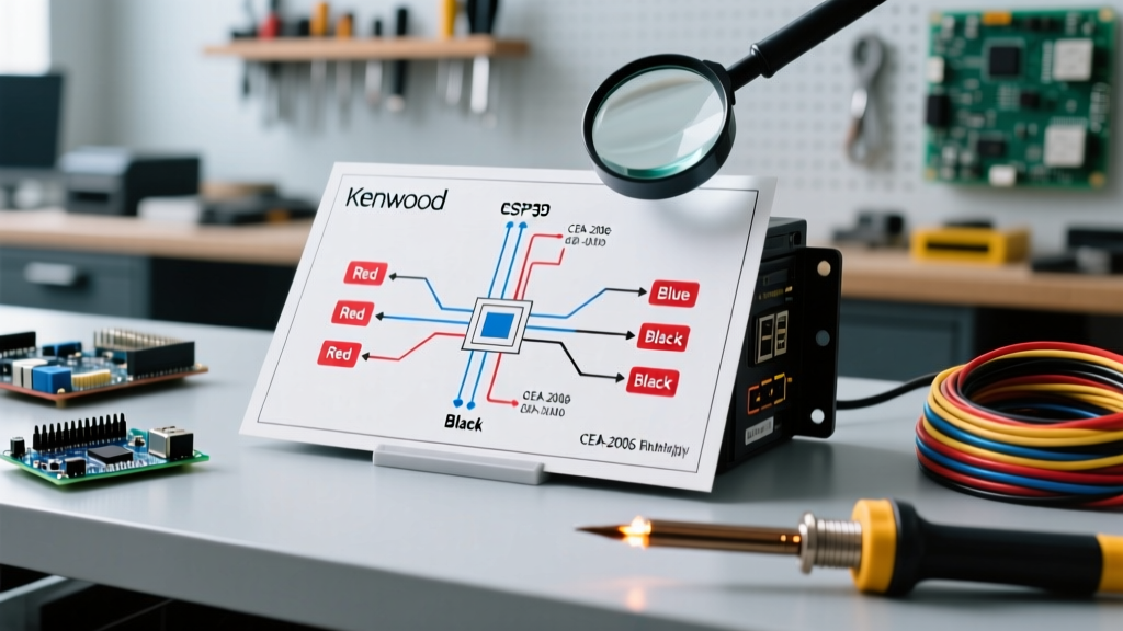
When searching for a wiring diagram for a Kenwood head unit, you are typically looking at the industry-standard 16-pin ISO/Molex connector used across their Excelon, DMX, and DPX series (such as the DDX9907XR or DMX709S). In 2026, while wireless CarPlay and Android Auto handle the data, the physical 12V DC power and speaker wiring remain strictly bound by the Consumer Technology Association (CTA) CEA-2006 color code standards. Misinterpreting these diagrams is a leading cause of 12V electrical fires, parasitic battery drains, and fried vehicle CAN-bus systems.
Unlike home audio, automotive and marine 12V DC environments are hostile. They subject wiring to extreme thermal cycling, vibration, and corrosive elements. According to the Mobile Electronics Certification Program (MECP), over 40% of aftermarket head unit failures are traced back to improper termination and grounding, rather than the head unit itself. Below is the definitive safety breakdown of the Kenwood 16-pin power and speaker harness.
CEA-2006 Pinout & Safety Matrix
| Wire Color | Function | Safety & Code Compliance Note |
|---|---|---|
| Yellow | Constant 12V (Battery/Memory) | Must be fused within 18 inches of the power source per SAE J1171. Do not tap into high-current ECU lines. |
| Red | Switched 12V (Ignition) | Never bridge Red and Yellow at the harness. This defeats sleep-mode protocols and causes parasitic drain. |
| Black | Chassis Ground | Must terminate to bare, unpainted metal. Avoid sharing ground bolts with sensitive ABS or SRS modules. |
| Orange / Orange-White | Illumination / Dimmer | Verify voltage with a multimeter. Some modern vehicles output PWM signals, not 12V, which can fry the Kenwood dimmer circuit. |
| Blue / Blue-White | Power Antenna / Amp Turn-On | Max current draw is typically 300mA. Use a 30A Bosch-style relay if triggering multiple high-draw amplifiers. |
| White/Gray/Green/Purple | Speaker Outputs (+ and -) | Never ground speaker wires. Kenwood Excelon units use BTL (Bridge-Tied Load) amplifiers; grounding a speaker wire will instantly destroy the internal IC. |
Critical Code Compliance: Marine, RV, and Off-Road
Installing a Kenwood marine receiver (like the KMM-BT328U) or mounting a standard unit in an RV requires strict adherence to specialized electrical codes. Standard automotive wiring practices are illegal and highly dangerous in these environments.
Marine Environments (ABYC E-11 Compliance)
For boat installations, the American Boat & Yacht Council (ABYC) mandates strict adherence to the E-11 standard for DC electrical systems. The most critical rule involves wire composition. You must use UL 1426 listed tinned copper wire. Standard copper-clad aluminum (CCA) wire, which is common in cheap aftermarket harness adapters, is strictly prohibited. CCA wire suffers from galvanic corrosion when exposed to marine humidity, leading to high-resistance connections that generate extreme heat and cause fires. Furthermore, all connections must be sealed against moisture intrusion using adhesive-lined heat shrink.
RV and Camper Vans (NFPA 1192 & NEC Article 551)
In recreational vehicles, the National Electrical Code (NEC) Article 551 and NFPA 1192 dictate that low-voltage DC wiring must be physically separated from 120V AC wiring by at least 1.5 inches, or separated by a physical barrier. When routing your Kenwood constant 12V and ignition wires through an RV dashboard, ensure they do not share a conduit with the inverter's AC lines to prevent inductive interference and severe shock hazards.
The Grounding Controversy: Chassis vs. Battery
The wiring diagram for a Kenwood head unit simply labels the black wire as 'Ground'. However, *where* you ground it dictates the noise floor and safety of the installation.
- The Factory Chassis Ground: In older vehicles, grounding to a nearby factory bolt is standard. However, in 2026 vehicles with complex CAN-bus networks and high-impedance sensors, sharing a factory ground point can introduce alternator whine or, worse, inject voltage spikes back into the vehicle's ECU.
- The Dedicated Ground Run: MECP-certified installers recommend running a dedicated 12 AWG ground wire from the head unit's black pigtail directly to a verified, sanded bare-metal point on the main chassis unibody, completely independent of factory wiring harnesses.
- Ground Loop Isolators: If you must use a shared ground and experience alternator whine, do not simply add a ground loop isolator to the RCA cables. Address the root cause by installing a PAC GTH-200 ground loop isolator on the 12V power line, or better yet, reroute the ground.
2026 Bill of Materials (BOM) for Safe Termination
Proper termination is non-negotiable. Twist connectors (Scotchloks) and standard electrical tape are banned in professional and marine installations due to vibration-induced loosening and adhesive degradation. Use the following professional-grade materials:
| Item | Specification | Est. Cost (2026) |
|---|---|---|
| Primary Wire | 18 AWG Tinned Copper (UL 1426 / SAE J1128) | $0.45 / ft |
| Heat Shrink | 3M EPS300 Adhesive-Lined (Dual Wall) | $14.99 / pack |
| Crimping Tool | Milwaukee M12 Cordless Crimper or Titan TIT11020 | $129.00 |
| Inline Fuse Holder | Blue Sea Systems ATC/ATO Waterproof | $8.50 |
| Wire Loom | Split Loom Tubing with Tesa 51036 Tape | $12.00 |
Step-by-Step Safe Termination Protocol
- Disconnect the Battery: Always disconnect the negative terminal of the vehicle battery before cutting or splicing any wires. Modern airbag systems (SRS) can deploy if a short occurs on a shared circuit.
- Strip and Crimp: Strip exactly 5/16 inch of insulation. Use a ratcheting crimper to apply a nylon-insulated butt connector. The crimp must pass the 'pull test' (firmly tugging the wire to ensure the copper strands are cold-welded inside the barrel).
- Seal with Adhesive Heat Shrink: Slide 3M EPS300 heat shrink over the connection. Apply heat from the center outward until the adhesive seals out of the ends. This creates a waterproof, vibration-proof bond that meets ABYC marine standards.
- Calculate Voltage Drop: If you are extending the Yellow constant 12V wire directly to the battery (recommended for high-draw units like the DDX9907XR), use the Blue Sea Systems Circuit Wizard to calculate the correct wire gauge. A standard 18 AWG wire is only safe for runs up to 10 feet on a 10A circuit. For longer runs in large trucks or RVs, step up to 14 AWG or 12 AWG to prevent voltage drop and overheating.
Common Failure Modes & Troubleshooting
Warning: Never solder 12V automotive connections in high-vibration zones. Solder creates a rigid point that causes the copper wire to work-harden and snap just outside the solder joint. Crimping with adhesive heat shrink remains the gold standard for automotive and marine environments.
The 'Melted ISO Connector' Syndrome
If your Kenwood head unit randomly reboots when the volume is turned up, inspect the main 16-pin ISO connector. The Yellow and Black pins carry the highest current. If the aftermarket harness adapter uses undersized, cheap brass terminals instead of phosphor-bronze or copper-alloy terminals, the resistance will generate heat. This melts the plastic housing, causing intermittent contact. Always inspect the male and female pins for black soot or warped plastic, and replace the adapter harness with an OEM-grade Metra or PAC kit if damage is found.
Parasitic Drain from CAN-Bus Interference
In vehicles with advanced start/stop technology and aggressive battery management systems (BMS), tapping the Red (switched) wire into a fuse that never truly 'sleeps' (like a 12V accessory socket) will drain the battery in 48 hours. Always use a multimeter to verify that the Red wire source drops to 0V exactly when the vehicle's CAN-bus goes to sleep (usually 15-20 minutes after locking the doors).
Frequently Asked Questions
Can I use the Kenwood wiring diagram for a different brand's harness?
No. While the CEA-2006 standard dictates that Yellow is constant 12V and Red is switched, proprietary features like steering wheel controls, OEM amplifier integration (A2B/CMOST), and parking brake bypass wires vary wildly between Kenwood, Pioneer, and Alpine. Always use a vehicle-specific integration module (like an iDatalink Maestro or Axxess interface) that maps the Kenwood pinout to the vehicle's specific data bus.
Why does the wiring diagram show a purple/white wire for the reverse camera?
The purple/white wire is the 'Reverse Gear Trigger'. When the vehicle is shifted into reverse, this wire receives 12V, telling the Kenwood screen to switch to the camera input. In modern vehicles with PWM (Pulse Width Modulated) reverse lights, the voltage fluctuates rapidly. You must install a 12V DC relay or a PAC TR-4 trigger module to convert the PWM signal into a clean 12V trigger for the Kenwood head unit, otherwise, the camera feed will flicker or fail to engage.
Is it safe to run the Kenwood head unit without a fuse on the yellow wire?
Absolutely not. While the Kenwood harness includes a 10A blade fuse, that fuse only protects the head unit's internal circuitry. It does not protect the wire running through your vehicle's dashboard. If the wire chafes against a sharp metal bracket under the dash, it will draw hundreds of amps from the battery, melting the wire insulation and starting a fire before the head unit's fuse even has a chance to blow. An inline fuse within 18 inches of the battery or power tap is a strict code requirement.