
The Anatomy of a Code-Compliant Sub-Panel Installation
Installing a sub-panel is one of the most common ways to expand your home or workshop's electrical capacity in 2026, whether you are powering a new EV charger, a detached garage, or a heavy-duty woodworking shop. However, the transition from a main service panel to a sub-panel introduces critical safety and code compliance variables. A standard wiring diagram for sub panel configurations differs fundamentally from a main panel diagram, primarily regarding how neutral and ground conductors are handled.
The National Electrical Code (NEC) strictly governs these installations to prevent shock hazards, fire risks, and equipment damage. According to the National Fire Protection Association (NFPA), improper sub-panel wiring remains a leading cause of residential electrical fires. This guide provides a deep-dive into the exact feeder sizing, grounding electrode requirements, and termination torque specs required for a flawless, inspector-approved installation.
Decoding the Wiring Diagram for Sub Panel Feeders
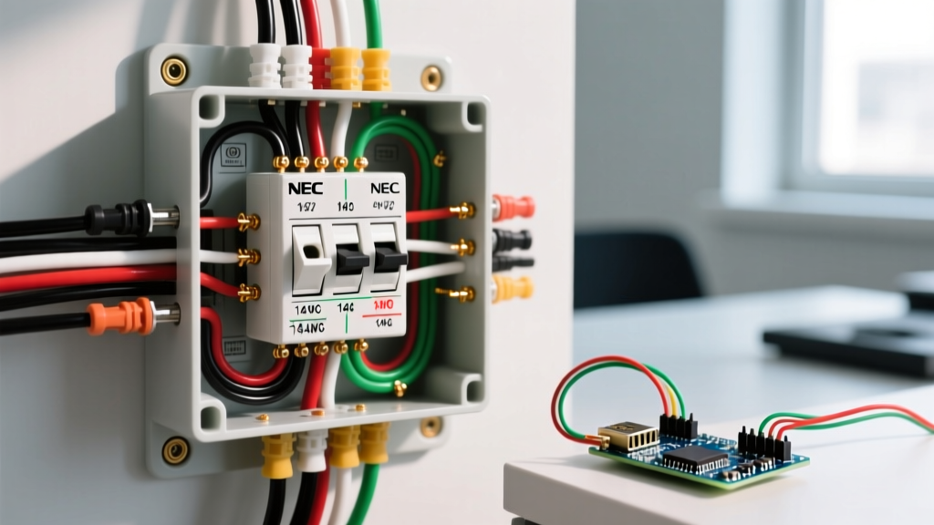
Unlike older 3-wire feeder setups (which were grandfathered out of the NEC decades ago), a modern, code-compliant wiring diagram for a sub-panel mandates a 4-wire feeder system. This includes:
- Two Hot Conductors (X & Y): Carrying 120V each, 180 degrees out of phase, providing 240V across both and 120V from either to neutral.
- One Neutral Conductor (W): The grounded conductor that carries unbalanced return current. It must be completely isolated from the ground bus and the panel enclosure.
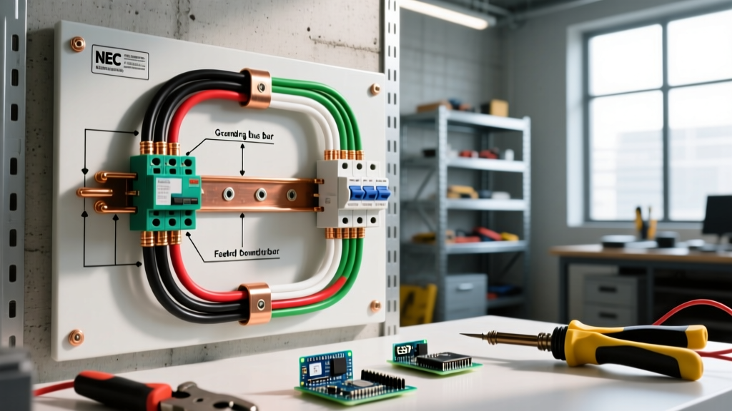
- One Equipment Grounding Conductor (EGC): The bare or green insulated wire that provides a low-impedance fault current path back to the main panel to trip the breaker during a short circuit.
⚠️ CRITICAL SAFETY WARNING: Never bond the neutral bus bar to the ground bus bar or the metal enclosure in a sub-panel. Doing so creates parallel paths for neutral current to flow on the grounding system, violating NEC Article 250.6 (Objectionable Current) and creating a severe shock hazard.
Feeder Sizing Matrix: Copper vs. Aluminum (75°C Column)
Selecting the correct wire gauge is dictated by NEC Article 310.15 and the 75°C column of the ampacity tables, as most modern breakers and lugs are rated for 75°C. Aluminum (specifically XHHW-2 or SER cable) has become the industry standard in 2026 for sub-panel feeders due to copper price volatility, often costing 60% less per foot.
| Sub-Panel Rating | Copper (THHN/THWN-2) | Aluminum (XHHW-2 / SER) | Max Run for <3% Voltage Drop (240V) |
|---|---|---|---|
| 60 Amp | #6 AWG | #4 AWG | ~110 feet |
| 100 Amp | #3 AWG | #1 AWG | ~130 feet |
| 125 Amp | #2 AWG | #1/0 AWG | ~140 feet |
| 200 Amp | #2/0 AWG | #4/0 AWG | ~160 feet |
Note: If your feeder run exceeds the maximum distances listed above, you must upsize the conductors by one or two gauge sizes to mitigate voltage drop, which can cause motor burnout and inefficient EV charging.
The Fatal Flaw: Neutral-to-Ground Bonding Violations
The most frequent failure point during municipal electrical inspections is the improper bonding of the neutral and ground bars. In a main service disconnect, the utility neutral is bonded to the earth ground and the panel chassis. This establishes the zero-reference voltage for the entire premises.
However, in a sub-panel, the neutral bus must float. Manufacturers like Square D and Eaton ship sub-panels with a green bonding screw or a metal bonding strap. This screw or strap must be removed before energizing the panel. If left in place, normal unbalanced neutral current (e.g., 15 amps returning from a 120V lighting circuit) will split between the neutral wire and the equipment grounding wire. This energizes the metal enclosures of appliances, conduit, and the panel itself, posing a lethal shock risk to anyone who bridges the gap to earth.
Grounding Electrode Systems for Detached Buildings
If your wiring diagram for a sub-panel extends to a detached structure (like a barn or detached garage), NEC Article 250.32(B) requires a local Grounding Electrode System (GES) at the second building. This typically involves driving two 5/8-inch copper-clad steel ground rods, spaced at least 6 feet apart, and connecting them to the sub-panel's ground bus using a minimum #6 AWG bare copper Grounding Electrode Conductor (GEC).
This local earth ground does not replace the equipment grounding conductor (EGC) run back to the main panel; it supplements it by stabilizing voltage during lightning strikes and line surges. The Electrical Safety Foundation International (ESFI) emphasizes that relying solely on ground rods without a continuous EGC back to the source is a catastrophic code violation that will prevent breakers from tripping during a fault.
Termination Torque & Mechanical Specifics
In 2026, inspectors routinely use calibrated torque screwdrivers to verify lug terminations. NEC 110.14(D) mandates that connections be torqued to the manufacturer's specified values. Under-torqued aluminum lugs suffer from thermal cycling loosening, leading to high-resistance arcing and fires.
- #4 AWG Aluminum: Typically requires 35 to 40 inch-pounds.
- #1 AWG Aluminum: Typically requires 45 to 50 inch-pounds.
- #2/0 AWG Aluminum: Typically requires 60 to 75 inch-pounds.
Always apply an antioxidant compound (such as Noalox or Penetrox) to stripped aluminum conductors before insertion to prevent galvanic corrosion and oxidation at the termination point.
Modern Code Nuance: NEC 120.12 and Solar Backfeed
If your sub-panel will host solar inverters or battery backup systems (like a Tesla Powerwall), you must adhere to NEC 120.12 busbar sizing rules. The sum of the main breaker rating and the solar backfeed breaker rating cannot exceed 120% of the panel's busbar rating. For a 100A sub-panel with a 100A main feeder breaker, the busbar can handle a maximum of 20A of solar backfeed (100 + 20 = 120). If you plan for heavy solar integration, oversizing the sub-panel busbar to 125A or 200A during the initial rough-in is highly recommended.
2026 Material Cost Breakdown: 100-Amp Sub-Panel
Budgeting accurately requires current market pricing. Here is a realistic estimate for a 100-amp, 12-space sub-panel installation using aluminum SER cable over a 50-foot run:
- 100A Sub-Panel Enclosure (e.g., Square D QO or Eaton BR): $85 - $130
- 50 ft of 1-1-1-3 AL SER Cable: $140 - $175 ($2.80 - $3.50/ft)
- 100A 2-Pole Breaker (Main Panel Feed): $45 - $70
- Miscellaneous (Conduit, fittings, anti-oxidant, ground bar): $60 - $90
- Total Material Cost: $330 - $465 (Excluding labor and permits)
Frequently Asked Questions (FAQ)
Can I use a main breaker panel as a sub-panel?
Yes. You can use a panel with a main disconnect breaker as a sub-panel, provided you remove the neutral-to-ground bonding strap or screw. The main breaker in the sub-panel will simply act as a local disconnect switch and must be rated equal to or higher than the feeder breaker in the main panel.
Does a sub-panel in the same building need ground rods?
No. NEC 250.32(A) states that a grounding electrode system is only required for separate structures. If the sub-panel is in an attached garage or a finished basement of the same primary building, the equipment grounding conductor run with the feeder is sufficient.
What happens if I don't isolate the neutral bar?
Failing to isolate the neutral bar causes neutral current to flow on the grounding wires, conduit, and appliance chassis. As highlighted by OSHA's electrical safety guidelines, this stray voltage can result in severe electrical shocks, interfere with sensitive electronics, and cause ground-fault circuit interrupters (GFCIs) to trip unpredictably or fail to trip when needed.