
Mastering the Wiring Diagram for Rule Automatic Bilge Pumps
When it comes to marine DC motor circuits, few applications are as critical as keeping water out of the hull. Rule Industries (now part of Flowtech) sets the benchmark for marine water evacuation, but even the best hardware will fail if the electrical foundation is flawed. This motor wiring tutorial breaks down the exact wiring diagram for Rule automatic bilge pump systems, focusing on ABYC-compliant practices, voltage drop mitigation, and fail-safe manual overrides.
Unlike standard automotive DC motors, marine bilge pump motors operate in highly corrosive, high-vibration environments. A proper wiring schematic must account for inrush current, stray current corrosion, and the absolute necessity of a manual override in the event of a float switch failure. In 2026, with the rising cost of marine vessel repairs, executing this wiring correctly the first time saves hundreds of dollars in potential water damage and electrical troubleshooting.
⚠️ ABYC E-11 Compliance Warning: According to the American Boat and Yacht Council (ABYC) E-11 standard, overcurrent protection (fuses or circuit breakers) must be installed within 7 inches of the battery connection point. If this is physically impossible, the maximum allowable distance is 72 inches, provided the wire is enclosed in a continuous sheath or conduit. Never rely on the boat's main battery switch to protect a bilge pump circuit; the pump must be wired directly to the battery or a dedicated always-hot bus bar to ensure it operates when the vessel is unattended.Core Components & 2026 Market Pricing
Before mapping out the wiring diagram for a Rule automatic bilge pump, you must select the correct hardware. The standard setup requires four primary components:
- The Pump Motor: The ubiquitous Rule 1100 GPH (Model 1100GPH) remains the industry standard for vessels up to 28 feet. As of 2026, it retails for approximately $55 to $65.
- The Float Switch: The Rule-A-Matic 40A (Model 16A) external float switch ($35) is preferred for its high amp rating and mercury-free design.
- The 3-Way Panel Switch: A Blue Sea Systems 9001E or Carling equivalent ($30–$45) provides Auto, Off, and Manual override capabilities.
- Marine-Grade Conductor: Tinned copper wire (such as Ancor Marine Grade) is mandatory to prevent black-wire corrosion.
Wire Gauge & Overcurrent Protection Matrix
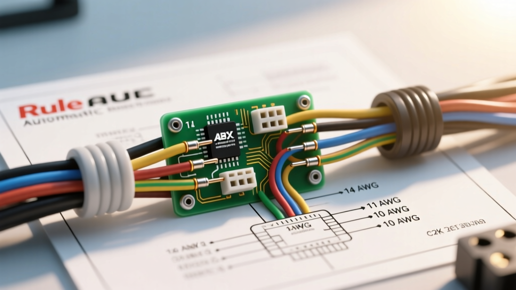
Sizing the wire and fuse correctly is the most common point of failure in DIY bilge pump installations. DC motors experience a high inrush current (locked rotor amperage) upon startup, which can be 3 to 5 times the running amperage. The West Marine Wire Size Advisor and ABYC tables dictate that wire gauge must be selected based on the maximum circuit length (positive + negative return) to keep voltage drop below 3%.
| Rule Pump Model | Capacity (GPH) | Max Running Amps (12V) | Required Fuse (Slow-Blow) | Min. Wire Gauge (15ft Total Run) | Min. Wire Gauge (25ft Total Run) |
|---|---|---|---|---|---|
| Rule 500 (Model 25D) | 500 | 2.5A | 5A | 16 AWG | 14 AWG |
| Rule 1100 (Model 1100GPH) | 1100 | 3.1A | 5A | 14 AWG | 12 AWG |
| Rule 2000 (Model 20D) | 2000 | 8.4A | 10A | 12 AWG | 10 AWG |
| Rule 3700 (Model 37D) | 3700 | 15.2A | 20A | 10 AWG | 8 AWG |
Step-by-Step Motor Wiring Tutorial
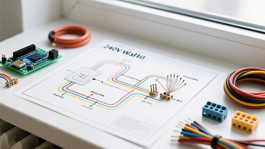
The following steps outline the standard wiring diagram for a Rule automatic bilge pump utilizing an external float switch and a manual 3-way override panel switch.
- Route the Positive Feed: Run a continuous length of red tinned copper wire from the positive terminal of the battery (or always-hot distribution bus) to the input terminal of your inline fuse holder. Install the appropriately sized slow-blow fuse.
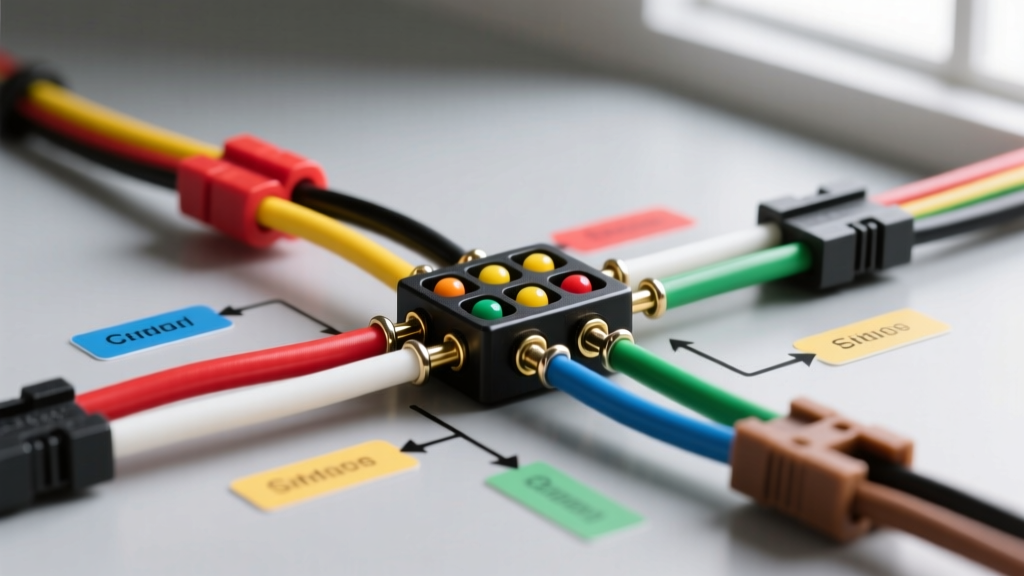
- Wire the 3-Way Switch: Route the fused positive wire to the center (common) terminal of the 3-way panel switch. This ensures that both the 'Auto' and 'Manual' positions receive protected power.
- Connect the Manual Override: Run a brown wire from the 'Manual' terminal on the 3-way switch directly to the positive (brown) lead of the Rule bilge pump motor. This bypasses the float switch, allowing you to force the motor to run in an emergency.
- Integrate the Float Switch: Run a wire from the 'Auto' terminal on the 3-way switch to one terminal of the Rule-A-Matic float switch. From the second terminal on the float switch, run a brown wire down to the bilge and connect it to the pump's positive (brown) lead using a waterproof, adhesive-lined heat shrink butt connector.
- Terminate the Ground: Connect the pump's black (negative) wire to the vessel's DC negative bus bar. Ensure the bus bar is properly bonded to the battery negative. Do not ground the pump directly to the engine block or a random hull bolt.
Internal Sensor vs. External Float Switch Topologies
It is vital to distinguish between standard Rule pumps and the Rule-Mate series. Standard models (like the 1100GPH) are dumb motors; they require the external switching logic detailed above. Rule-Mate pumps, however, feature an internal solid-state electronic water sensor.
When wiring a Rule-Mate automatic bilge pump, the wiring diagram simplifies significantly: constant 12V power is routed through a fuse and a simple 2-way (On/Off) manual switch directly to the pump's brown wire. The internal sensor handles the automatic triggering. However, marine surveyors heavily favor external float switches for primary bilges because internal sensors can fail due to oil, diesel, or heavy sludge coating the electronic contacts.
Advanced Troubleshooting & Failure Modes
Voltage Drop and Motor Stall
Permanent magnet DC motors are highly sensitive to voltage drop. If your wiring is undersized or connections are corroded, the voltage at the motor terminals may drop below 10.5V under load. When this happens, the motor will hum, the impeller will fail to spin, and the amp draw will skyrocket to the locked-rotor amperage level, eventually blowing the fuse. Always measure voltage at the pump terminals while the motor is running to verify circuit health.
The 'Ghost Pump' Phenomenon
If your Rule bilge pump turns on and off randomly when the bilge is bone dry, you are likely experiencing stray current interference or a failing float switch. Debris such as fishing line or dog hair can wrap around the float switch hinge, causing it to bind in the 'up' position. Alternatively, if the wiring diagram was executed poorly and the positive wire is chafing against the aluminum hull or engine block, stray current can trick the circuit. Inspect all wire runs for abrasion and use split-loom tubing in high-vibration areas.
Centrifugal Switch Failures in Older Models
Some legacy Rule automatic pumps utilized an internal mechanical centrifugal switch rather than electronic sensors. These switches are notorious for carbon buildup on the contact points. If you are maintaining an older vessel, upgrading to a modern external float switch topology or a solid-state Rule-Mate unit is highly recommended for reliable 2026 marine safety standards.
Final Commissioning Checklist
- Verify the inline fuse is within 7 inches of the power source.
- Pour 5 gallons of water into the bilge to test the float switch activation point.
- Toggle the 3-way panel switch to 'Manual' to verify emergency override functionality.
- Check all submersible connections for adhesive-lined heat shrink (standard vinyl electrical tape will peel off in water within weeks).
- Confirm the pump discharges water through the transom or hull fitting without backflow.
For complete hardware specifications and replacement impeller diagrams, consult the official Flowtech Rule Marine Bilge Pumps catalog. Proper execution of this wiring diagram ensures your vessel remains safe, dry, and compliant with marine insurance requirements.