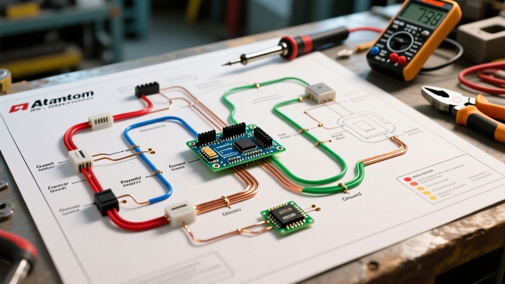

Decoding the Atwood Water Heater Electrical Architecture
When servicing, upgrading, or troubleshooting an RV water heating system, accessing an accurate wiring diagram for Atwood water heater models is the critical first step. Originally manufactured by Atwood Mobile Products and now fully integrated under the Dometic umbrella as of 2026, these units remain the gold standard for recreational vehicles. The most common configurations—such as the G6A-8E (6-gallon gas) and the GC6AA-10E (10-gallon gas/electric combo)—rely on a dual-voltage architecture that separates 12V DC control circuits from 120V AC heating elements.
Misinterpreting the wiring schematic is the leading cause of blown ignition modules, tripped main panel breakers, and catastrophic thermal cutoff failures. This comprehensive reference guide breaks down the exact circuit paths, wire gauges, and termination points required to safely wire and diagnose these systems in compliance with modern RV electrical standards.
The Dual-Voltage Reality: 12V DC vs. 120V AC
The most common mistake DIYers make when referencing an Atwood schematic is conflating the DC and AC sides of the system. The gas ignition, flame sensing, and control logic operate strictly on 12V DC power drawn from the RV’s house battery bank. Conversely, the electric heating element (found only in "E" or combo models) operates on 120V AC shore power or inverter power.
Modern Lithium BMS Considerations (2026 Update)
With the mass adoption of Lithium Iron Phosphate (LiFePO4) battery banks in modern RVs, the 12V DC charging voltage can frequently reach 14.4V to 14.6V during the absorption phase. The legacy Atwood and modern Dometic ignition control boards (Part #93863) are rated to handle up to 15V DC continuously. However, if your multimeter reads above 15.2V at the water heater's 12V terminal block, you risk frying the logic board. Always verify your DC-DC converter output before connecting the red 12V power wire.
Wiring Reference Matrix: Wire Colors and Gauges
The following table outlines the standard color-coding and American Wire Gauge (AWG) requirements for the GC6AA-10E combo unit. Note that while Atwood/Dometic strictly adheres to these colors at the factory, previous owners or aftermarket technicians may have altered the RV-side wiring.
| Wire Color | Gauge (AWG) | Voltage | Function | Termination Point |
|---|---|---|---|---|
| Red | 14 AWG | 12V DC | Main Power to Thermostat | RV 12V Fuse Panel (5A/10A) |
| White (DC) | 14 AWG | 12V DC | Ground Return | RV Chassis Ground Bus |
| Black | 12 AWG | 120V AC | Hot to Heating Element | RV AC Breaker Panel (15A/20A) |
| White (AC) | 12 AWG | 120V AC | Neutral Return | RV AC Neutral Bus Bar |
| Green / Bare | 12 AWG | N/A | Safety Chassis Ground | RV AC Ground Bus Bar |
Gas Ignition Circuit Path (12V DC Side)
The 12V DC side controls the gas valve solenoid, the spark electrode, and the flame sense probe. Tracing this circuit is essential when the unit fails to ignite or clicks continuously without lighting.
- Power Entry: 12V DC enters the system via the 14 AWG Red wire, passing first through the RV's interior on/off rocker switch.
- Operating Thermostat: The current flows to the 12V snap-disc operating thermostat. This switch closes at 110°F and opens at 140°F. If the water is cold, the circuit remains closed, allowing voltage to pass.
- High Limit Switch (ECO): The current then passes through the High Limit switch, which is a safety device designed to open the circuit if the water temperature exceeds 180°F.
- Ignition Module Board: Voltage reaches the Dometic/Atwood ignition module. The board initiates a 15-second spark sequence and opens the gas valve solenoid.
- Flame Sense: Once the gas ignites, the flame rectification circuit detects a microamp current (typically 2.0 to 5.0 µA) through the flame sense probe, signaling the board to stop sparking and hold the gas valve open.
Expert Troubleshooting Tip: If your spark electrode is clicking but the gas valve never opens (no "clunk" sound), check the spark gap. It must be precisely 1/8 inch (3.17 mm). A gap that is too wide will draw excessive current from the ignition board, causing the internal safety relay to drop the gas valve circuit to protect the board.
Electric Heating Element Circuit Path (120V AC Side)
The 120V AC side is entirely independent of the 12V DC gas logic. It is responsible for powering the 1440W Incoloy heating element (Part #91535). According to the NFPA 1192 Standard on Recreational Vehicles, all 120V AC water heating elements must be protected by a dedicated breaker and properly grounded to the chassis.
- AC Power Entry: 120V AC enters via the 12 AWG Black wire from a dedicated 15A or 20A breaker on the RV's main distribution panel.
- AC Thermostat & High Limit: The hot wire passes through a separate 120V AC thermostat and a 180°F thermal cutoff switch located on the exterior tank flange.
- Heating Element: The current flows through the 1440W element, generating heat, and returns via the 12 AWG White (Neutral) wire.
Warning: Never apply 120V AC to the 12V DC terminal block. Doing so will instantly destroy the ignition module and pose a severe electrocution hazard. Always use a non-contact voltage tester to verify the absence of AC voltage before touching the DC control wires.
Multimeter Troubleshooting Matrix
When the wiring diagram indicates a component should be passing current, use a digital multimeter to verify the following baseline readings. These values assume the system is disconnected from power and isolated for resistance (Ohms) or continuity testing.
| Component | Expected Multimeter Reading | Failure Symptom | Corrective Action |
|---|---|---|---|
| 12V Operating Thermostat | 0.1 - 0.5 Ohms (Closed) | No spark, no gas flow | Replace 12V snap-disc thermostat |
| 120V Heating Element | 9.5 - 10.5 Ohms | Water won't heat on shore power | Replace 1440W element (Part #91535) |
| ECO Thermal Fuse (180°F) | 0 Ohms (Continuous) | System completely dead on one side | Replace one-time use thermal fuse |
| Flame Sense Probe | 2.0 - 5.0 µA (Live DC Test) | Sparks, lights, then shuts off after 3s | Clean probe with steel wool; check ground |
| Gas Valve Solenoid | 70 - 90 Ohms | Clicks but no gas, or no click at all | Replace gas valve assembly |
Critical Safety Protocols and RVIA Compliance
Adhering to the RV Industry Association (RVIA) best practices is non-negotiable when modifying or repairing Atwood water heater wiring. The Dometic official service documentation explicitly mandates that all 120V AC connections must utilize crimped, insulated ring terminals secured with a torque screwdriver to prevent arcing inside the exterior access panel.
Furthermore, the exterior metal jacket of the water heater must be bonded to the RV's main AC ground bus using a minimum 12 AWG green or bare copper wire. This bonding ensures that if the internal 120V heating element sheath cracks and leaks current into the water tank, the RV's main GFCI or standard breaker will trip immediately, protecting the end-user from lethal shock hazards.
By strictly following the wiring diagram paths, respecting the dual-voltage isolation, and verifying component resistance with a multimeter, you can ensure your Atwood water heater operates safely and efficiently for thousands of miles of travel.