
Understanding the Split-System HVAC Control Architecture
Deciphering a wiring diagram for furnace with AC configurations requires a clear understanding of how low-voltage control circuits interact with high-voltage power distribution. In a standard residential split-system—comprising an indoor gas furnace and an outdoor electric condenser—the indoor furnace control board acts as the central nervous system. It routes 24VAC power from the transformer to the thermostat, interprets heating and cooling calls, and subsequently triggers the outdoor contactor and indoor blower motor.
Whether you are upgrading to a modern smart thermostat, replacing a burnt-out contactor, or diagnosing a blown control board fuse, understanding the exact terminal mappings and voltage pathways is critical. This guide breaks down the schematic logic using industry-standard equipment, such as the Goodman GM9S96 gas furnace (featuring the IGM-02 control board) paired with a GSX14 outdoor condenser, reflecting standard 2026 residential HVAC installations.
Core Components of the Furnace and AC Circuit
Before tracing the wires, you must identify the primary nodes in the schematic:
- Step-Down Transformer: Converts 120VAC line voltage from the furnace's main power supply down to 24VAC for the control circuit. Typically rated at 40VA (Volt-Amps).
- Integrated Control Board (IGM): The printed circuit board (PCB) inside the furnace featuring terminal strips for thermostat inputs (R, W, Y, G, C) and high-voltage outputs for the blower motor.
- Outdoor Contactor: An electromagnetically operated switch in the condenser unit. Its 24V coil receives the signal from the furnace board to close the high-voltage contacts, sending 240V to the compressor.
- Thermostat: The user interface that bridges the 24VAC 'Hot' (R) to various function terminals (W, Y, G) to initiate a sequence of operation.
Thermostat to Control Board Terminal Mapping
The backbone of any furnace and AC wiring diagram is the 18/5 solid copper thermostat cable. In 2026, a standard 250-foot spool of 18/5 CL2-rated wire costs approximately $35 to $45. Below is the universal color-code and terminal mapping for a standard single-stage cooling and single-stage heating system.
| Wire Color | Thermostat Terminal | Furnace Board Terminal | Function | Typical Voltage State |
|---|---|---|---|---|
| Red | R (or Rc/Rh) | R | 24VAC Hot Supply | Constant 24-28VAC to C |
| White | W (or W1) | W | Heating Call | 24VAC when calling for heat |
| Yellow | Y (or Y1) | Y | Cooling Call (Contactor) | 24VAC when calling for cool |
| Green | G | G | Indoor Blower Fan | 24VAC when fan is requested |
| Blue/Black | C | C | 24VAC Common Return | 0V (Reference Ground) |
When the thermostat calls for cooling, an internal relay (or solid-state switch) bridges the R and Y terminals. This sends 24VAC down the Yellow wire to the 'Y' terminal on the furnace control board. The board's microcontroller detects this voltage, initiates a pre-purge sequence for the inducer motor (if configured), and then closes its own internal Y relay to send 24VAC out to the outdoor condenser.
The Outdoor Contactor Circuit: Wiring the Condenser
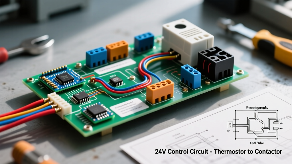
The most common point of confusion when reading a wiring diagram for furnace with AC systems is how the indoor board communicates with the outdoor unit. This is achieved via a separate 2-conductor cable (typically 18/2 aluminum or copper-clad wire) that runs from the furnace control board to the outdoor disconnect and into the condenser cabinet.
Tracing the Y and C Pathway
- Furnace Board Output: The 'Y' and 'C' terminals on the furnace board are wired to the 18/2 cable.
- Disconnect Box: The low-voltage wires pass through the weatherproof disconnect box alongside the high-voltage wires. NEC compliance requires low-voltage and high-voltage wires to be separated by a physical barrier or at least 2 inches of airspace to prevent inductive interference and short-circuit hazards.
- Contactor Coil: Inside the condenser, the 18/2 wires connect to the A1 and A2 terminals on the contactor coil. The coil typically has a resistance of 10 to 30 ohms. When 24VAC is applied, it generates a magnetic field that pulls the heavy-duty contacts closed.
Safety Warning: Always turn off the 120V breaker for the furnace and pull the 240V disconnect block for the outdoor condenser before opening any electrical panels. The 24V control circuit remains live as long as the furnace transformer is energized.
High-Voltage Branch Circuit and Disconnect Wiring
While the 24V circuit handles the logic, the high-voltage circuit handles the heavy lifting. According to the National Electrical Code (NFPA 70), specifically Article 440 governing Air-Conditioning and Refrigerating Equipment, the outdoor condenser requires a dedicated branch circuit and a localized disconnect switch.
- Breaker Panel: A 30-Amp, double-pole breaker supplies 240VAC.
- Feeder Cable: 10/2 NM-B (Romex) with a bare copper ground is standard for 30A circuits up to 50 feet.
- Disconnect Box: A 60-Amp, non-fused pull-out disconnect must be installed within sight of the condenser unit. This allows technicians to physically lock out power during maintenance.
- Whip Connection: A liquid-tight flexible metallic conduit (LFMC) containing THHN wires connects the disconnect to the condenser's internal control box.
Diagnosing the 3-Amp Control Board Fuse
If you are consulting a wiring diagram because your AC has stopped working and the thermostat is blank, you are likely dealing with a blown 3-Amp ATC automotive fuse located on the furnace control board. This is the most frequent failure mode in split-system HVAC wiring.
Why Does the 3A Fuse Blow?
The 3A fuse protects the 40VA step-down transformer from catastrophic failure. 40VA divided by 24V equals roughly 1.66 Amps of continuous draw. A 3A fuse allows for brief inrush currents when the contactor coil energizes. The fuse blows almost exclusively due to a dead short to ground on the 24V wiring.
Common Short Locations:
- Condenser Cabinet Rub-Through: The 18/2 wire entering the outdoor unit vibrates against the sharp sheet metal or the copper refrigerant lines, wearing away the insulation and shorting the 'Y' wire to the grounded chassis.
- Rodent Damage: Mice and squirrels frequently chew on the low-voltage thermostat wires inside the outdoor unit or attic spaces, crossing the 24V hot with the ground.
- Failing Contactor Coil: Over time, the insulation inside the contactor's electromagnetic coil breaks down, creating an internal short that instantly pops the board fuse when the thermostat calls for cooling.
Step-by-Step Multimeter Diagnostics
Use a digital multimeter (like the Fluke 117) set to VAC and Ohms to isolate the fault:
- Verify Transformer Output: Measure across the R and C terminals on the board. You should read between 24VAC and 28VAC. If you read 0V, check the 3A fuse for continuity.
- Isolate the Short: If the fuse is blown, disconnect the 18/2 wires going to the outdoor unit from the Y and C terminals on the furnace board.
- Test the Coil: Set your multimeter to Ohms (Ω). Place the probes on the 18/2 wires you just disconnected. A healthy contactor coil will read between 10Ω and 30Ω. If it reads 0.0Ω (dead short) or OL (open circuit), the outdoor contactor must be replaced (typically a $25 to $45 part).
- Test the Wire Run: If the coil tests fine, the short is in the 18/2 wire running through the walls or yard. You will need to pull a new 18/2 cable.
Smart Thermostat Upgrades and the C-Wire Requirement
In 2026, upgrading to advanced smart thermostats like the Ecobee SmartThermostat Premium or the 4th Gen Nest Learning Thermostat is a common home improvement project. These devices require continuous 24VAC power to operate their Wi-Fi radios and displays, which is supplied via the 'C' (Common) wire.
When referencing your furnace wiring diagram, ensure the control board has an available 'C' terminal. Modern boards like the Honeywell ST9120U or Goodman IGM series feature multiple 'C' spades or terminal screws. If your existing thermostat cable only has 4 wires (R, W, Y, G) and lacks a C-wire, do not attempt to use the ground wire as a common return; this will trip GFCI breakers and cause erratic board behavior. Instead, use a spare wire in the existing bundle, pull a new 18/5 cable, or install a 24VAC Add-A-Wire diode kit to multiplex the signals.
Maintenance and Efficiency Standards
Proper wiring and component maintenance directly impact the seasonal energy efficiency ratio (SEER) and annual fuel utilization efficiency (AFUE) of your system. Loose low-voltage connections can cause the contactor to chatter, leading to pitted contacts, voltage drops, and compressor hard-starting. The U.S. Department of Energy strongly recommends annual inspections of all electrical connections, contactor points, and transformer outputs to maintain peak efficiency and prevent premature compressor failure.
By mastering the wiring diagram for furnace with AC systems, you transition from simply replacing parts to truly understanding the electromechanical logic that keeps your home comfortable year-round. Always prioritize safety, adhere to local NEC codes, and verify every connection with a multimeter before restoring power.