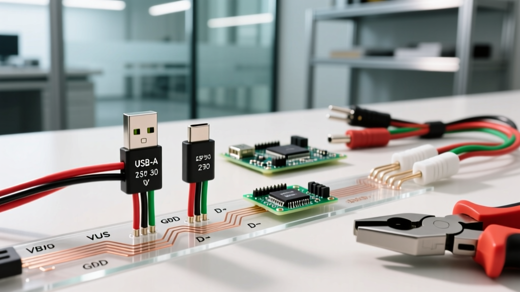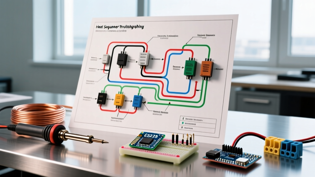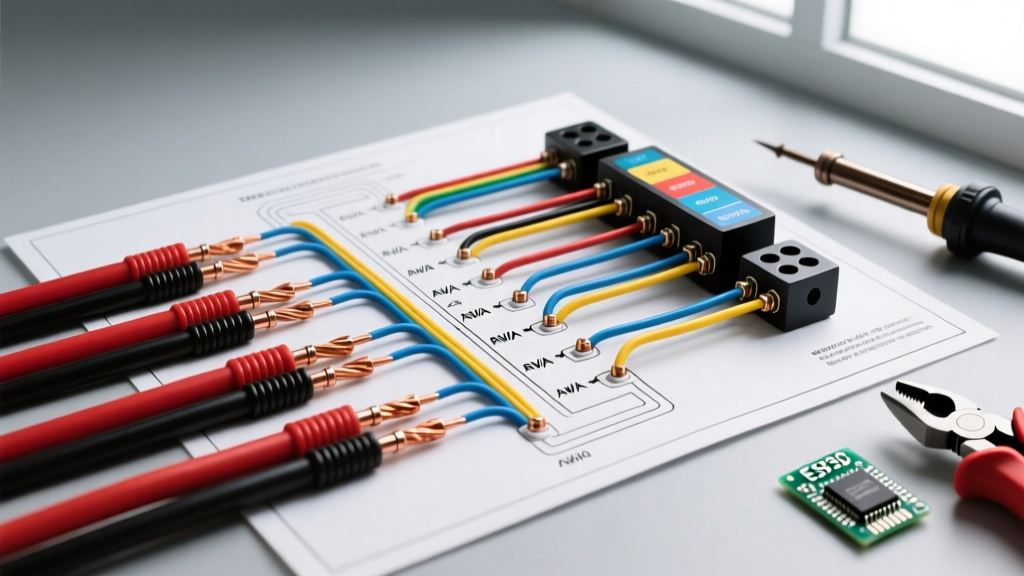

The Anatomy of an Electric Brake Controller Wiring Diagram
Installing an aftermarket electric brake controller is one of the most critical safety upgrades you can make to your tow vehicle. Whether you are wiring a proportional powerhouse like the Tekonsha Prodigy P3, a modern PWM-based Redarc Tow-Pro Elite V3, or the Curt Spectrum, the underlying electrical principles remain identical. A flawless electric brake controller wiring diagram relies on three pillars: correct wire gauge selection to minimize voltage drop, strict adherence to RVIA color codes, and proper circuit protection.
As of 2026, modern inertial and PWM (Pulse Width Modulation) controllers are highly sensitive to voltage fluctuations. While older time-delayed controllers could tolerate a sloppy ground or undersized wiring, today’s microprocessors will throw error codes or deliver inconsistent braking force if the power delivery is compromised. This guide breaks down the exact specifications, routing techniques, and color standards required for a professional-grade installation.
The 7-Way RV Blade Connection Point
Before running wires under the dash, you must understand the vehicle-to-trailer interface. The 7-way RV blade connector is the industry standard. For the brake controller, you are primarily concerned with three pins:
- Pin 2 (Electric Brakes): Carries the modulated DC voltage from the controller to the trailer magnets.
- Pin 4 (12V Auxiliary): Often used to charge the trailer’s breakaway battery, but distinct from the brake controller’s main power feed.
- Pin 1 (Ground): The common ground return path for the entire trailer lighting and braking system.
Expert Insight: Never rely solely on the 7-way plug’s ground pin to return high-amperage brake current. Always run a dedicated, heavy-gauge ground wire from the controller directly to the vehicle chassis or battery negative terminal to prevent ground loops.
Wire Gauge Selection Matrix: Beating Voltage Drop
The most common mistake DIYers make is using 14 AWG or 16 AWG wire for the main power and brake output lines. While these gauges are fine for LED marker lights, electric brake magnets draw significant current. A single 10-inch brake magnet draws roughly 3.0 to 3.5 amps at 12V. A twin-axle trailer (4 magnets) can pull 12 to 14 amps continuously during a hard stop, with initial inrush spikes hitting much higher.
According to guidelines referenced by the etrailer.com Wiring FAQ, voltage drop over long wire runs can starve the trailer brakes of the power needed to lock the drums. With copper prices stabilizing in 2026, 10 AWG primary wire averages about $1.80 per foot, making it a cost-effective insurance policy against brake fade.
| Trailer Configuration | Total Magnet Draw (Approx) | Run Length (Under 15 ft) | Run Length (15 ft - 25 ft) | Run Length (Over 25 ft) |
|---|---|---|---|---|
| Single Axle (2 Brakes) | 6 - 8 Amps | 12 AWG | 12 AWG | 10 AWG |
| Tandem Axle (4 Brakes) | 12 - 14 Amps | 12 AWG | 10 AWG | 10 AWG |
| Tri-Axle (6 Brakes) | 18 - 21 Amps | 10 AWG | 10 AWG | 8 AWG |
RVIA Color Code Standards vs. Aftermarket Pigtails
The Recreational Vehicle Industry Association (RVIA) establishes the baseline color codes for RV and trailer wiring. However, when you purchase an aftermarket controller, the included 4-wire pigtail may occasionally deviate, especially on budget or imported units. Always verify the wiring legend printed on the controller’s housing.
The Standard 4-Wire Controller Harness
- White (Ground): Connects to a clean, bare-metal point on the vehicle chassis or directly to the negative battery terminal. Failure Mode: A poor ground causes the controller display to dim when brakes are applied, or triggers an ‘OL’ (Overload) error.
- Black (12V Power Input): Routes directly from the vehicle’s positive battery terminal, passing through an auto-reset circuit breaker. This provides the raw amperage that the controller modulates and sends to the trailer.
- Red (Stoplight Switch Signal): Connects to the vehicle’stoplight switch circuit (usually the cold side of the brake pedal switch). This wire draws less than 0.5 amps and simply tells the controller’s microprocessor that the driver has pressed the brake pedal. Warning: Tapping into the wrong wire here (like a multiplexed CAN-bus line on modern trucks) can trigger dashboard check-engine lights. Use a dedicated stoplight relay module for 2020+ vehicles.
- Blue (Brake Output): The modulated power output that travels from the controller, through the vehicle’s 7-way connector (Pin 2), and down to the trailer brakes.
Circuit Breaker Sizing and the 18-Inch Rule
Your electric brake controller wiring diagram is incomplete without proper overcurrent protection. The National Electrical Code (NEC) and automotive best practices dictate that any unfused wire connected directly to a battery must be protected as close to the power source as possible.
The 18-Inch Rule
The circuit breaker must be installed within 18 inches of the positive battery terminal. If a collision or chafing event shorts the main power wire before it reaches a breaker located under the dash, the wire will act as a heating element, potentially causing an engine bay fire.
Sizing the Auto-Reset Breaker
Use only automotive-grade, auto-resetting thermal circuit breakers (typically Bussmann or Littelfuse brands, costing between $8 and $15 in 2026). Do not use standard blade fuses for the main high-amperage brake lines, as the inrush current of cold brake magnets can cause nuisance blowing.
- 20-Amp Breaker: Suitable for single-axle trailers (2 brakes).
- 30-Amp Breaker: The industry standard for tandem-axle trailers (4 brakes) and most standard RVs.
- 40-Amp Breaker: Required for heavy-duty tri-axle or quad-axle setups (6 to 8 brakes).
Pro-Level Termination and Routing Techniques
The longevity of your wiring depends entirely on how the connections are terminated. The vibration of towing will quickly shake loose poorly crimped connections, leading to intermittent braking.
- Strip and Crimp: Use a high-quality ratcheting wire crimper. Strip exactly 3/8-inch of insulation. Insert the wire into a nickel-plated copper ring terminal. Nickel plating prevents the galvanic corrosion that occurs when copper meets steel battery posts.
- Adhesive Heat Shrink: Never use standard vinyl electrical tape to seal your crimps. Use dual-wall, adhesive-lined heat shrink tubing. When heated, the inner meltable adhesive wall flows into the wire strands, creating a waterproof seal that blocks capillary action and green corrosion.
- Routing: Route the blue output wire and black power wire away from the vehicle’s exhaust system and moving steering shafts. Secure the loom every 12 inches using UV-resistant zip ties or rubber-coated P-clamps.
- Dielectric Grease: Apply a small dab of dielectric grease to the 7-way plug pins and the controller’s rear harness connector to prevent moisture ingress and oxidation.
Troubleshooting Common Wiring Failures
Even with a perfect diagram, real-world variables can introduce faults. According to Tekonsha Technical Support, over 80% of controller error codes are traced back to wiring issues outside the controller itself.
Controller Displays ‘SH’ (Short Circuit)
This indicates the blue output wire is touching ground somewhere between the controller and the trailer magnets. Check the 7-way plug for bent pins bridging the brake pin (Pin 2) and the ground pin (Pin 1). Inspect the trailer’s umbilical cord for chafing where it enters the A-frame.
Controller Displays ‘OL’ (Overload)
An overload error means the controller is detecting resistance that is too low, drawing more current than it can safely handle. This is almost always caused by a ground loop or a shorted brake magnet coil inside the trailer drum. Disconnect the trailer and test the controller with a known-good test light; if the error clears, the fault is in the trailer’s wiring or magnets.
Erratic Braking or Display Dimming
If the controller screen dims when you apply the brakes, or the trailer brakes pulse inconsistently, you have severe voltage drop. This is typically caused by an undersized ground wire (White) or a corroded chassis ground point. Sand the paint and primer off the chassis down to bare, shiny metal, apply a star washer to bite into the metal, and torque the ground bolt to at least 15 ft-lbs.
Final Verification Steps
Before hooking up your trailer, use a digital multimeter to verify the voltage at the vehicle’s 7-way plug. With the vehicle running and the manual override lever on the controller fully engaged, you should read between 11.8V and 12.4V at Pin 2. If you read below 11.0V, your wire gauge is too thin, your connections are corroded, or your vehicle’s alternator is struggling to keep up with the load. Mastering these wire gauge and color code fundamentals ensures your rig stops safely, predictably, and legally on every highway descent.