
Understanding the Wiring Diagram for Ceiling Fan with Light
Installing a ceiling fan with an integrated light kit requires more than just matching wire colors; it demands strict adherence to the National Electrical Code (NEC) to prevent catastrophic mechanical failures and electrical fires. Unlike standard light fixtures, ceiling fans introduce dynamic vibration and continuous mechanical load, while the addition of a light kit increases the overall amperage draw and heat generation within the canopy.
This comprehensive guide breaks down the standard wiring diagram for ceiling fan with light configurations, focusing heavily on NEC code compliance, proper junction box ratings, and precise wire gauge selections for 2026 residential standards.
The Core Dual-Switch Wiring Diagram
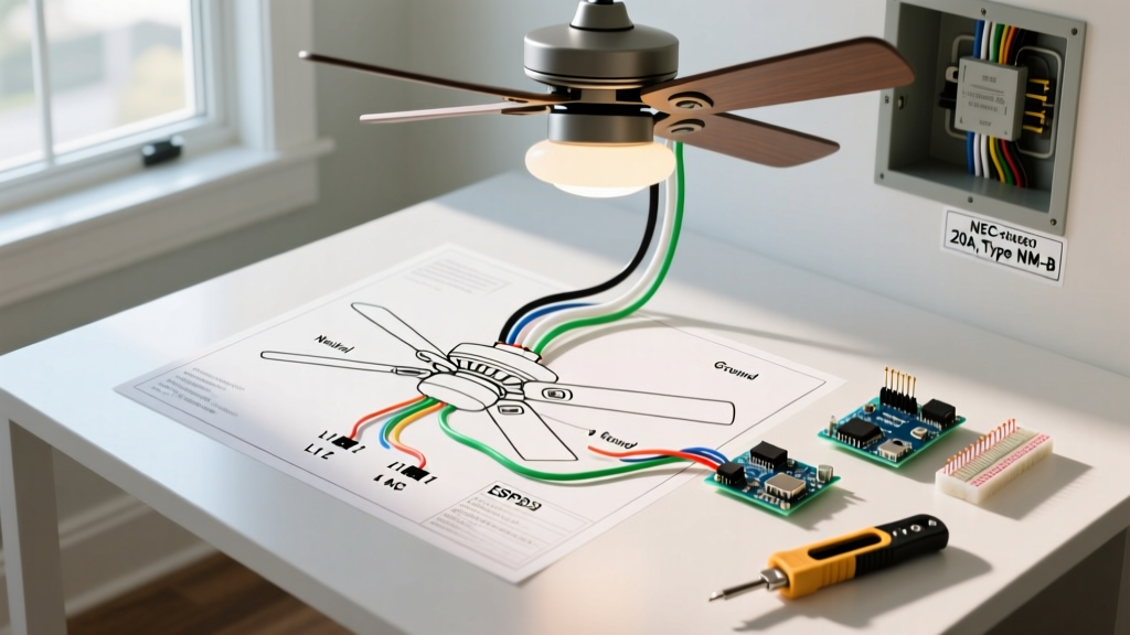
The most common and code-compliant method for independently controlling a ceiling fan and its light kit from a single wall location is utilizing a 3-wire cable (typically 14/3 or 12/3 NM-B Romex) paired with a dual-switch or two separate single-pole switches.
Wire Color Mapping & Functionality
- Black Wire (Line/Load 1): Carries the switched hot from the first wall switch to the ceiling fan motor (usually connects to the black wire on the fan).
- Red Wire (Line/Load 2): Carries the switched hot from the second wall switch to the light kit (usually connects to the blue wire on the fan).
- White Wire (Neutral): Completes the circuit. Connects to the white neutral wires from both the fan motor and the light kit.
- Bare/Green Wire (Ground): Bonds the metal junction box, the fan mounting bracket, and the fan's internal ground wire to the home's grounding electrode system.
Expert Insight: Never use the ground wire as a substitute for a neutral conductor (a dangerous practice known as a 'bootleg neutral'). This violates NEC Article 250.148 and creates a severe shock hazard if the ground path is ever compromised.
Critical NEC Code Requirements: Box Ratings & Support
The most frequent code violation in ceiling fan installations is mounting the unit to a standard light fixture junction box. According to NEC Article 314.27(A), outlet boxes must be listed and marked as acceptable for ceiling fan support if a fan is to be installed.
Weight Limits and Approved Hardware
Standard round or octagonal light fixture boxes are typically rated for a maximum static load of 35 pounds. A fully assembled ceiling fan with a glass light kit can easily weigh between 45 and 65 pounds, not including the dynamic torque generated when the motor spins.
- Fans under 35 lbs: Can be mounted to boxes specifically marked 'Acceptable for Fan Support'. Examples include the Raco Model 937 4-Inch Round Fan-Rated Box.
- Fans between 35 and 70 lbs: Require heavy-duty fan-rated boxes that mount directly to the building structure (joists) or utilize rated adjustable braces.
- Fans over 70 lbs: The NEC mandates that the fan must be supported independently of the outlet box, usually requiring direct lag-screw mounting into a structural ceiling joist.
Recommended Hardware: For retrofit installations where attic access is unavailable, the Westinghouse Saf-T-Brace (Model 0103000) is a UL-listed, expandable steel brace that secures between joists and provides a robust 4-inch fan-rated box capable of supporting up to 150 lbs.
Wire Gauge, Amperage, and Breaker Matrix
Selecting the correct wire gauge is dictated by the overcurrent protection device (breaker) protecting the circuit. While ceiling fans are highly efficient (often drawing less than 1.5 amps on high), the integrated light kit can draw significantly more, especially if non-LED bulbs are used.
| Breaker Size | Min. Wire Gauge (NM-B) | Max Continuous Load (80%) | Fan + Light Kit Scenario | NEC AFCI Requirement |
|---|---|---|---|---|
| 15 Amp | 14 AWG (14/3) | 12 Amps (1,440W) | Standard 52' Fan + 4x60W Incandescent | Required in Bedrooms, Living Rooms |
| 20 Amp | 12 AWG (12/3) | 16 Amps (1,920W) | Large 60' Fan + High-Lumen LED/Halogen | Required in Bedrooms, Living Rooms |
2026 Code Update Note: Under recent NEC Article 210.12 expansions, Arc-Fault Circuit Interrupter (AFCI) protection is now mandatory for almost all 120V, single-phase, 15- and 20-amp branch circuits supplying outlets in residential living spaces. Ensure your dual-switch setup is fed from an AFCI breaker or utilizes an AFCI receptacle upstream.
Step-by-Step Canopy Wiring & Grounding
Once the fan-rated box is secured and the 3-wire cable is pulled, follow these precise steps for the canopy connections. Always strip exactly 3/4-inch of insulation from solid copper conductors to ensure maximum contact area inside the wire nut without exposing bare wire below the skirt.
- Establish the Ground Bond: Connect the bare copper supply wire to the green ground wire from the fan, the green ground from the light kit, and the green grounding pigtail attached to the metal ceiling mounting bracket. Use a green wire nut or a standard Ideal 341 Orange Wire-Nut.
- Terminate the Neutrals: Twist the white supply wire together with the white wire from the fan motor and the white wire from the light kit. Secure with an Ideal 342 Yellow Wire-Nut. Give each wire a firm tug to ensure mechanical retention.
- Connect the Fan Load: Connect the black supply wire (from Switch 1) to the black wire on the ceiling fan.
- Connect the Light Load: Connect the red supply wire (from Switch 2) to the blue wire on the ceiling fan (which routes power specifically to the light kit).
- Canopy Management: Carefully fold the wires into the junction box. Do not force them, as pinching the insulation against the metal box edge can cause a short circuit over time due to fan vibration.
Safety Failure Modes and Edge Cases
Even with a correct wiring diagram for ceiling fan with light setups, specific edge cases can lead to dangerous failure modes if ignored during installation.
1. Multi-Wire Branch Circuits (MWBC) and Shared Neutrals
If your dual switches are fed from a Multi-Wire Branch Circuit (two hot wires on different phases sharing a single neutral), NEC Article 210.4 requires a simultaneous disconnect mechanism. This means the two breakers must be tied together with a handle tie or be a single double-pole breaker. If an electrician turns off only one breaker to service the fan, the shared neutral can carry return current from the active phase, resulting in a lethal shock hazard.
2. Dimmer Switch Incompatibility
A common DIY error is installing a standard incandescent dimmer switch on the wall to control the ceiling fan motor speed. Standard dimmers chop the AC sine wave, which will cause an AC induction fan motor to overheat, hum violently, and eventually catch fire. Only use switches specifically rated for fan speed control (e.g., Lutron Diva DVFQ) on the black fan wire, and standard LED-compatible dimmers on the red light wire.
3. Vibration-Induced Wire Nut Loosening
Because ceiling fans generate continuous harmonic vibration, standard smooth wire nuts can gradually back off over several years. Always use winged wire nuts with internal steel coils (like the Ideal WingNut series) and wrap the base of the connection with high-quality 3M Super 33+ vinyl electrical tape to provide an additional mechanical barrier against vibration.
Authoritative Resources for Electrical Safety
For further reading on electrical safety, appliance wiring standards, and energy efficiency guidelines for ceiling fans, consult the following authoritative resources:
- National Fire Protection Association (NFPA): National Electrical Code (NEC) - The definitive source for all US electrical installation codes and junction box rating mandates.
- U.S. Consumer Product Safety Commission (CPSC): Home Electrical Systems - Vital safety guides regarding shock hazards, grounding, and DIY electrical risks.
- ENERGY STAR: Certified Ceiling Fans - Specifications on motor efficiency, amperage draws, and lighting kit integrations for modern code compliance.