
Decoding the Wiring Diagram for Coleman Furnace Systems
Interpreting the wiring diagram for Coleman furnace models—particularly the high-efficiency Echelon TM9V, TM8V, and the reliable DG8 series—requires more than just matching colors to terminals. Modern Coleman Integrated Control Modules (ICMs) are highly sensitive to voltage drops, improper grounding, and reversed polarity. A single miswired 24VAC thermostat connection can instantly blow the 3-amp or 5-amp automotive-style fuse on the control board, leaving your system dead in the middle of winter.
This comprehensive reference guide bridges the gap between the factory schematic and real-world installation. We will break down the exact wire gauge requirements, standard color code mappings, and internal component wiring specifics necessary to ensure your Coleman gas furnace operates safely and efficiently in 2026 and beyond.
High-Voltage vs. Low-Voltage Boundaries
Before pulling any wire, you must respect the physical separation mandated by the National Electrical Code (NEC). High-voltage (120VAC) and low-voltage (24VAC) wiring must never share the same conduit or knockouts. On Coleman furnaces, the 120VAC supply enters through a dedicated junction box on the vestibule panel, while the 24VAC thermostat wires enter through a separate rubber grommet on the side of the casing.
Thermostat Wiring: Color Codes and Gauge Requirements
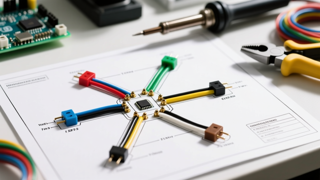
The most common point of failure when installing or replacing a Coleman furnace control board is the thermostat low-voltage wiring. While the industry relies on standard color codes, Coleman ICMs use specific terminal designations that you must map correctly.
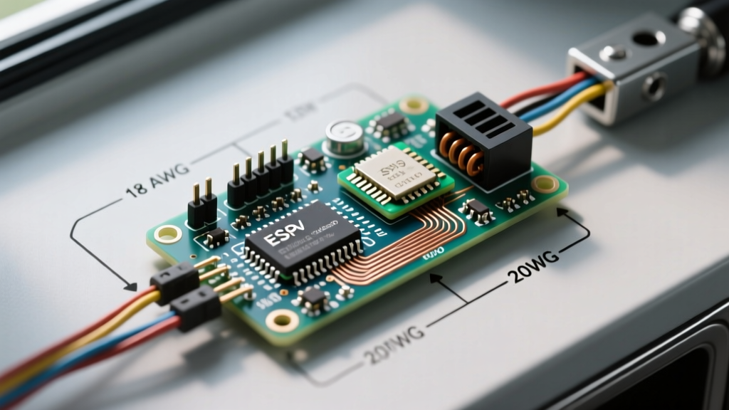
For standard residential runs under 50 feet, 18 AWG solid copper thermostat wire (typically 18/5 or 18/8) is required. If your run exceeds 50 feet, or if you are powering a Wi-Fi smart thermostat with a power-hungry display, you must step up to 16 AWG to prevent voltage drop below the 20VAC minimum required by the Coleman gas valve.
| Terminal Label | Standard Wire Color | Function | Coleman Specific Notes |
|---|---|---|---|
| R / RH / RC | Red | 24VAC Hot (Power) | Coleman boards typically jumper RH and RC internally. Use 'R' for single-stage. |
| W / W1 | White | First Stage Heat | Sends 24VAC to the gas valve and inducer relay. |
| W2 | Black (or Brown) | Second Stage Heat | Used on TM8V/TM9V two-stage models for high-fire gas valve solenoid. |
| Y / Y1 | Yellow | Cooling (Compressor) | Routes to the outdoor contactor. Must be paired with 'C' for smart stats. |
| G | Green | Indoor Blower Fan | Energizes the blower relay for continuous fan operation. |
| C / COM | Blue (or Black) | 24VAC Common | Critical: Do not confuse with Ground. Essential for Wi-Fi thermostats. |
Internal Component Wiring & Color Codes
Once inside the Coleman furnace vestibule, you will encounter the internal wiring harness. The factory uses specific color-coded wires with high-temperature insulation (typically rated for 105°C or higher) to handle the ambient heat near the heat exchanger.
Gas Valve and Igniter Connections
The Coleman gas valve (often manufactured by White-Rodgers or Honeywell for Coleman) operates on 24VAC. The wiring harness typically uses 18 AWG stranded wire with spade connectors.
- Red/Blue Wires: Main valve solenoid (24VAC).
- White/Black Wires: Secondary valve or modulation control (on variable-capacity TM9V models).
Failure Mode: Using solid thermostat wire instead of stranded wire for internal gas valve connections can lead to metal fatigue and wire breakage due to the vibration of the blower and inducer motors.
Pressure Switches and Limit Controls
The safety loop in a Coleman furnace relies on normally-open pressure switches and normally-closed high-limit switches.
- Orange/Purple Wires (18 AWG): Typically used for the primary and secondary draft pressure switches.
- White Wires (14 AWG High-Temp): Used for the main limit switch and auxiliary rollout switches located near the burner manifold.
According to U.S. Department of Energy guidelines, maintaining the integrity of these safety loops is paramount. Never bypass a limit switch with a standard wire nut; always use high-temperature ceramic wire nuts or crimp connectors rated for the heat exchanger vestibule environment.
ECM Blower Motor Connections (Echelon Series)
If you are wiring a modern Coleman Echelon variable-speed furnace, the blower motor is an ECM (Electronically Commutated Motor). You will not find standard wire nuts here. Instead, the motor connects to the ICM and the control module via specialized multi-pin Molex connectors:
- 5-Pin Power Plug: Carries 120VAC (Hot/Neutral), Ground, and 24VAC control power.
- 16-Pin Data Plug: Carries low-voltage DC signals from the ICM to dictate RPM and torque profiles based on the heating stage.
Warning: Never disconnect or reconnect the 16-pin data plug while the 120VAC power is live. Doing so will arc the low-voltage traces and permanently destroy the ECM motor control board, a replacement part that frequently exceeds $600 in 2026.
Wire Gauge Selection & Voltage Drop Matrix
Undersized thermostat wire is a silent killer of HVAC efficiency. If the voltage drops too low across a long wire run, the Coleman gas valve may chatter, fail to open, or the ICM may falsely read a thermostat short. Reference this matrix when planning your low-voltage runs:
| Wire Gauge (AWG) | Standard Load (Gas Valve + Relay) | Heavy Load (Wi-Fi Stat + Contactor) | Recommended Application |
|---|---|---|---|
| 20 AWG | Max 25 Feet | Not Recommended | Jumpers inside the furnace cabinet only. |
| 18 AWG | Max 50 Feet | Max 30 Feet | Standard residential single-stage installs. |
| 16 AWG | Max 90 Feet | Max 60 Feet | Long runs, smart thermostats, multi-stage. |
| 14 AWG | Max 150 Feet | Max 100 Feet | Commercial applications, zoning dampers. |
Common Wiring Failures and the 3-Amp Fuse Blowout
The most frequent service call related to the wiring diagram for a Coleman furnace involves a dead control board. The ICM is protected by a standard automotive ATC blade fuse (usually 3-Amp purple, or 5-Amp orange on older DG8 models).
Expert Troubleshooting Tip: If your Coleman furnace ICM LED flashes a 4-blink code or remains completely dark, check the blade fuse first. If the fuse is blown, do not just replace it. A blown fuse indicates a direct 24VAC short to ground or common.
Top 3 Causes of Blown ICM Fuses:
- The 'C' and 'G' Swap: Connecting the 24VAC Common wire to the 'G' (Fan) terminal at the thermostat. When the thermostat calls for fan, it shorts the transformer directly to ground through the blower relay coil.
- Chafed Outdoor Wire: The 18 AWG wire running to the outdoor AC contactor passes through the wall and rubs against sharp metal siding or copper refrigerant lines, eventually wearing the insulation and shorting 'Y' to ground.
- Improper Jumpering: Using a solid copper wire to jumper 'R' and 'W' for testing, and accidentally letting the bare end touch the grounded furnace chassis.
Code Compliance and Final Verification
When finalizing your wiring, ensure all 120VAC connections are secured with appropriately sized wire nuts (e.g., Ideal Yellow 221 for 14 AWG) and that no bare copper is exposed outside the nut. The NEC requires that the furnace be on a dedicated 15-amp or 20-amp branch circuit, and the grounding conductor must be securely bonded to the furnace chassis ground lug. Proper grounding is not just a safety requirement; the Coleman ICM uses chassis ground to verify flame rectification (the microamp signal that proves the burners are lit). A poor ground wire will result in the furnace lighting for 3 seconds and then shutting down, a failure mode often misdiagnosed as a bad flame sensor.
For deeper dives into schematic reading and control logic, consult resources like HVAC School's guide to wiring diagrams to master the symbology used in Coleman's factory documentation. Always kill the main breaker and verify zero voltage with a multimeter before touching any internal Coleman furnace wiring.