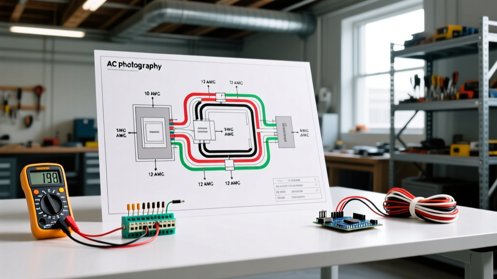

Decoding the Wiring Diagram for AC Unit Panel Connections
When homeowners and junior technicians search for a wiring diagram for AC unit setups, they typically focus on the low-voltage thermostat wires, the internal run capacitor, or the contactor relay. However, from a dedicated Panel & Breaker Guide perspective, the most critical and dangerous part of the schematic is the 240-volt feeder circuit connecting your main electrical service panel to the exterior condenser unit. Misinterpreting this section of the diagram leads to nuisance breaker tripping, voltage drop, melted wire insulation, and severe fire hazards.
In 2026, with the widespread adoption of high-efficiency variable-speed compressors and smart HVAC systems, understanding the exact panel-side requirements is more important than ever. This guide breaks down how to read the manufacturer data plate, size your breakers and wire gauges accurately, and execute a code-compliant installation from the main panel to the exterior disconnect.
The Data Plate: Your True Wiring Diagram
Before pulling any wire or installing a breaker, you must locate the manufacturer's data plate on the side of the condenser unit. This metal placard serves as the ultimate wiring diagram for AC unit electrical specifications. According to the National Electrical Code (NEC) Article 440, you must size your branch circuit based on two specific metrics found on this plate:
- MCA (Minimum Circuit Ampacity): This dictates the absolute minimum wire gauge required to safely carry the load without overheating. It is calculated using the compressor's Rated Load Amps (RLA) plus the fan motor's Full Load Amps (FLA), multiplied by 125%.
- MOCP (Maximum Overcurrent Protection): This is the maximum breaker size allowed to protect the unit from short circuits and ground faults, while still accommodating the massive inrush current (Locked Rotor Amps, or LRA) when the compressor starts.
Expert Insight: Never size your breaker based on the MCA. The MCA is for wire sizing; the MOCP is for breaker sizing. It is entirely common (and code-compliant) to use a 10 AWG wire (rated for 30A) on a 40A breaker, provided the MOCP on the data plate explicitly allows 40A and the manufacturer's internal overload protectors are rated for it.
Breaker and Wire Gauge Sizing Matrix
The following matrix provides standard panel-side requirements for modern 240V central air conditioning units. Always defer to your specific unit's data plate, as high-SEER models with variable-speed inverters may have lower MCA requirements than older single-stage units.
| Unit Capacity (Tons) | Typical MCA (Amps) | Typical MOCP (Breaker) | Minimum Copper Wire Gauge (THHN) | Recommended Panel Breaker Model |
|---|---|---|---|---|
| 1.5 Ton | 12A - 14A | 15A or 20A | 14 AWG | Square D HOM220 (20A) |
| 2.0 Ton | 15A - 18A | 20A or 25A | 12 AWG | Siemens Q225 (25A) |
| 2.5 Ton | 18A - 22A | 25A or 30A | 10 AWG | Eaton BR230 (30A) |
| 3.0 Ton | 22A - 26A | 30A or 35A | 10 AWG | Square D HOM230CP (30A) |
| 4.0 Ton | 28A - 33A | 35A or 40A | 8 AWG | Siemens Q240 (40A) |
| 5.0 Ton | 34A - 42A | 40A or 50A | 8 AWG or 6 AWG | Eaton BR250 (50A) |
Step-by-Step: Panel to Disconnect Wiring Procedure
Executing the physical wiring requires strict adherence to torque specifications and conduit fill ratios. Here is the professional workflow for routing power from the main panel to the exterior disconnect box.
1. Install the Double-Pole Breaker
Shut off the main service disconnect. Snap the 240V double-pole breaker into the panel bus bar. For a standard 3-ton unit requiring a 30A breaker, install a model like the Square D Homeline HOM230CP (retailing around $14 in 2026). Connect the black and red THHN feeder wires to the breaker terminals.
Critical E-E-A-T Step: NEC 110.14(D) mandates that all terminations be tightened to the manufacturer's specified torque. For the HOM230CP, the torque spec for 10 AWG copper is exactly 12 lb-in. Use a calibrated digital torque screwdriver (such as the CDI 401SM) to prevent loose connections that cause thermal expansion, arcing, and eventual panel fires.
2. Route Conduit and Pull Wire
Do not use direct-burial UF-B cable for modern AC installations; it is prone to physical damage and degrades under UV exposure if exposed. Instead, run 3/4-inch Schedule 40 PVC conduit from the panel to an exterior 60A non-fused pull-out disconnect (e.g., Eaton DT222NRP, approx. $22). Pull three individual THHN/THWN-2 conductors: Black (Hot 1), Red (Hot 2), and Green (Equipment Ground). For 10 AWG wire, the ground must also be 10 AWG.
3. Terminate at the Disconnect
Inside the disconnect box, land the Black and Red wires on the main lugs, and the Green wire on the dedicated ground busbar. Ensure the pull-out block is inserted securely. From the load side of the disconnect, you will run a short whip (usually flexible metallic conduit or liquid-tight flex) directly into the condenser's control box, following the internal wiring diagram for AC unit contactor terminals (L1 and L2).
Advanced Troubleshooting: Voltage Drop and Inrush Current
Even if your wiring diagram and breaker sizing are perfect, long wire runs can cause severe operational issues. According to the U.S. Department of Energy, under-voltage conditions force compressors to draw higher amperage to maintain mechanical output, leading to premature failure and voided warranties.
Calculating Voltage Drop
NEC 210.19(A) Informational Note recommends a maximum 3% voltage drop for branch circuits. For a 240V AC unit, 3% equals 7.2V. Let us calculate a real-world scenario:
- Scenario: 3-Ton unit drawing 22A, located 130 feet from the main panel, using 10 AWG copper wire.
- Formula: VD = (2 x K x I x D) / CM
- Variables: K (Copper) = 12.9 | I = 22A | D = 130 ft | CM (10 AWG Circular Mils) = 10,380
- Calculation: (2 x 12.9 x 22 x 130) / 10380 = 7.11V (2.96%)
This setup is just barely compliant. If the run was 150 feet, the drop would exceed 8.2V (3.4%), requiring you to upsize to 8 AWG wire, despite the MCA only calling for 10 AWG. Always perform voltage drop calculations for runs exceeding 75 feet.
Nuisance Tripping and Inrush Current
If your newly installed breaker trips instantly upon startup, you are likely experiencing an inrush current issue. Older single-stage compressors can draw 5 to 7 times their RLA for a fraction of a second when starting (Locked Rotor Amps). If you installed a standard thermal-magnetic breaker, the magnetic trip mechanism might misinterpret this inrush as a short circuit. Upgrading to a breaker with a specific HACR (Heating, Air Conditioning, and Refrigeration) rating, or installing a hard-start capacitor kit on the condenser, resolves this edge case.
Code Compliance and Final Safety Checks
Before energizing the circuit, verify compliance with EPA Energy Star installation guidelines and local AHJ (Authority Having Jurisdiction) requirements. Ensure the exterior disconnect is mounted within sight and readily accessible of the condenser unit, as mandated by NEC 440.14. Never rely solely on the main panel breaker as the disconnecting means, as emergency technicians require immediate local shutoff capabilities.
By treating the panel-to-disconnect feeder as the most vital part of your wiring diagram for AC unit project, you ensure a safe, efficient, and long-lasting cooling system capable of handling the peak electrical demands of modern summers.