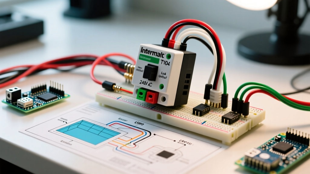

Understanding the 240V Pool Pump Timer Circuit
Wiring a pool pump timer is not like wiring a standard indoor light switch. Pool pumps are heavy inductive loads that require dedicated 240V circuits, strict adherence to NFPA 70 (National Electrical Code) Article 680, and precise equipotential bonding. In this motor wiring tutorial, we will break down the exact wiring diagram for pool pump timer installations, focusing on the industry-standard Intermatic T104 mechanical timer and modern 240V single-phase pump motors like the Hayward Super Pump and Pentair WhisperFlo.
CRITICAL SAFETY WARNING: Never work on a pool timer or pump motor without locking out the main panel breaker and verifying zero voltage with a CAT III or CAT IV multimeter. Water and 240V electricity are a lethal combination. Ensure your pool's 8 AWG solid copper bonding wire is continuous and unbroken before energizing the circuit.
Why the Intermatic T104 Remains the 2026 Industry Standard
Despite the rise of variable speed pumps (VSPs) with internal digital clocks, the Intermatic T104 (and its NEMA 3R outdoor variant, the T104P3) remains the most widely installed external timer for single-speed and dual-speed pool pumps. Priced between $95 and $125 in 2026, it features a heavy-duty 40-amp double-pole single-throw (DPST) switch capable of handling the high inrush current of 2 HP to 3 HP pool motors. Understanding its terminal layout is the key to mastering the wiring diagram for pool pump timer setups.
Decoding the Wiring Diagram for Pool Pump Timer Setups
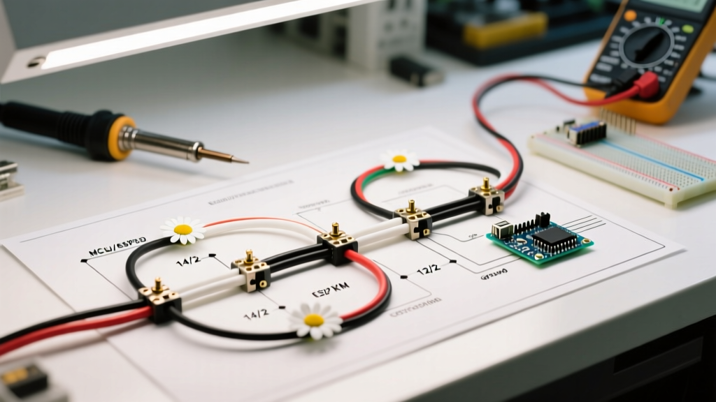
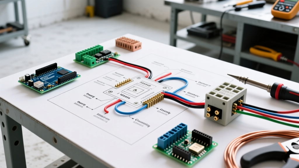
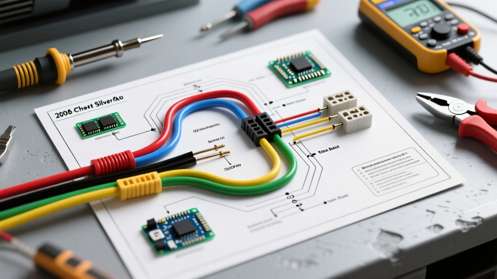
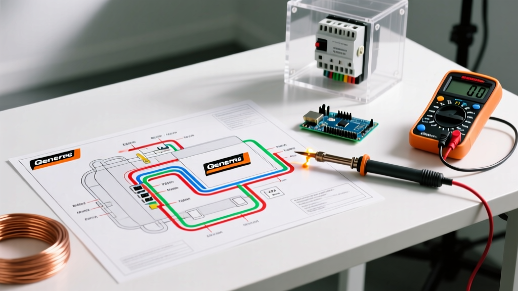
The core of the T104 wiring diagram relies on four main load-bearing terminals, plus a grounding bus. The timer acts as a mechanical relay, physically connecting and disconnecting both the L1 and L2 hot legs of your 240V supply simultaneously.
Line Side vs. Load Side Connections
- Terminal 1 (Line 1 In): Connects to the L1 hot wire coming from the main service panel breaker.
- Terminal 2 (Line 2 In): Connects to the L2 hot wire coming from the main service panel breaker.
- Terminal 3 (Load 1 Out): Connects to the L1 hot wire feeding the pool pump motor.
- Terminal 4 (Load 2 Out): Connects to the L2 hot wire feeding the pool pump motor.
- Ground Bus (GR): Connects the bare copper or green insulated equipment grounding conductor (EGC) from the panel to the EGC going to the pump motor.
Wire Gauge and Breaker Sizing Matrix
Selecting the correct wire gauge is critical to prevent voltage drop and thermal degradation. According to the U.S. Department of Energy's pool equipment guidelines, properly sizing your conductors ensures maximum motor efficiency and lifespan.
| Pump Motor HP | Breaker Size (Amps) | Min. Wire Gauge (Copper) | Max Run Distance (ft) | Timer Model Recommendation |
|---|---|---|---|---|
| 1.0 HP - 1.5 HP | 20A (2-Pole) | 12 AWG THWN | 60 ft | Intermatic T104 / WH40DLX |
| 2.0 HP - 2.5 HP | 30A (2-Pole) | 10 AWG THWN | 75 ft | Intermatic T104 / T104P3 |
| 3.0 HP+ | 40A (2-Pole) | 8 AWG THWN | 80 ft | Intermatic T10404 (w/ contactor) |
Step-by-Step Motor Wiring Tutorial
Follow this exact sequence to wire your timer and motor safely. This workflow assumes conduit runs (PVC or flexible metallic) from the panel to the timer, and from the timer to the pump.
- Terminate the Panel Side: At the main breaker panel, land the red and black 240V wires onto a new 2-pole breaker. Land the bare/green ground wire onto the equipment ground bus (never the neutral bus). Run these wires through the conduit to the timer enclosure.
- Wire the Timer Line Side: Strip 3/4 inch of insulation. Land the panel's L1 (black) on Timer Terminal 1, and L2 (red) on Timer Terminal 2. Land the ground wire on the timer's ground bus.
- Wire the Timer Load Side: Run a new set of 3 wires (Black, Red, Green) from the timer to the pool pump. Land the black wire on Terminal 3, the red wire on Terminal 4, and the green wire on the timer's ground bus.
- Terminate the Motor Side: Open the pool pump motor's wiring compartment. For a 240V configuration, ensure the motor's internal voltage selector (often a small switch or jumper on the terminal board) is set to 240V. Land the black wire on L1, the red wire on L2, and the green wire on the motor's internal ground screw.
- Establish Equipotential Bonding: Locate the external bonding lug on the outside of the pool pump motor casing. Connect the continuous 8 AWG solid bare copper bonding wire to this lug, ensuring it also connects to the pool shell, deck, and timer enclosure as per NEC 680.26.
Variable Speed Pump (VSP) Timer Bypass Considerations
If you are upgrading to a modern Variable Speed Pump (like the Pentair IntelliFlo3 VSF), the traditional wiring diagram for pool pump timer setups changes. VSPs have internal digital timers and should ideally receive continuous 240V power to maintain their internal memory and run self-diagnostics. However, local electrical codes or specific automation setups may still require an external disconnect or timer. In these cases, the Intermatic T104 is wired exactly as described above, but the trippers are removed, leaving the switch in the permanent 'ON' position, effectively using the T104 as a code-compliant external maintenance disconnect rather than a daily scheduler.
Advanced Troubleshooting and Failure Modes
When a pool pump fails to operate, electricians and DIYers often misdiagnose the issue. Here are specific failure modes related to timer and motor wiring:
The Clock Motor Runs, But the Dial Doesn't Turn
This is the most common mechanical failure. The 240V clock motor (a small synchronous motor geared to the dial) is spinning, but the main trippers are failing to catch the dial's actuator lever.
Fix: Replace the yellow plastic trippers (Intermatic part #156T1978). Do not attempt to bend the metal actuator lever, as this will alter the timing calibration.
The Timer Dial Doesn't Move at All
If the clock motor is dead, the timer will not advance.
Edge Case: If a DIYer previously wired a 120V Intermatic T101 timer into a 240V circuit without a neutral wire, or wired a 240V T104 into a 120V circuit, the clock motor will instantly fry. Always verify the timer model matches the circuit voltage before energizing.
The Pump Hums but Won't Spin
This is rarely a timer issue. If the timer is outputting 240V on Terminals 3 and 4, but the motor only hums, the issue is inside the motor.
Fix: Check the run capacitor (usually a black or silver cylinder on top of the motor). If it is bulging or reads outside its microfarad (µF) rating on a multimeter, replace it. If the capacitor is fine, the motor's internal centrifugal switch is likely stuck or the starting winding is burnt out, requiring a motor replacement.
Breaker Trips Instantly Upon Timer Engagement
If the 2-pole breaker trips the millisecond the timer turns 'ON', you have a dead short.
Fix: Inspect the conduit for water intrusion. Pool timer enclosures are prone to condensation and ant infestations, both of which can bridge Terminals 3 and 4 or bridge a hot terminal to the grounded metal enclosure. Clean the enclosure, check for melted wire insulation, and megger-test the motor windings to ground.