
Introduction: Treating Automotive HVAC as High-Draw Appliances
When approaching classic vehicle restoration or repair, it is highly effective to treat major automotive electrical subsystems exactly like household appliances. The heater and air conditioning blower motor in a 1989 C/K series pickup is essentially a 12V DC appliance that draws significant current, relies on a multi-speed resistor network, and utilizes a high-amperage relay for its maximum setting. As of 2026, these 37-year-old GMT400 platform harnesses are experiencing severe copper oxidation, melted connector housings, and increased resistance. Understanding how to read and apply a wiring diagram for 1989 Chevy truck models is no longer just about factory restoration; it is a critical diagnostic skill for preventing electrical fires and restoring proper climate control.
In this appliance-style wiring tutorial, we will dissect the GMT400 blower motor circuit, map the exact factory wire colors, and provide a modern relay-bypass upgrade to save your aging dashboard switch.
Expert Insight: The GM HVAC blower circuit is notorious for melting the 4-pin resistor connector. Do not simply replace the resistor block; you must address the voltage drop in the 35-year-old wiring leading to it, or the new component will melt within months.
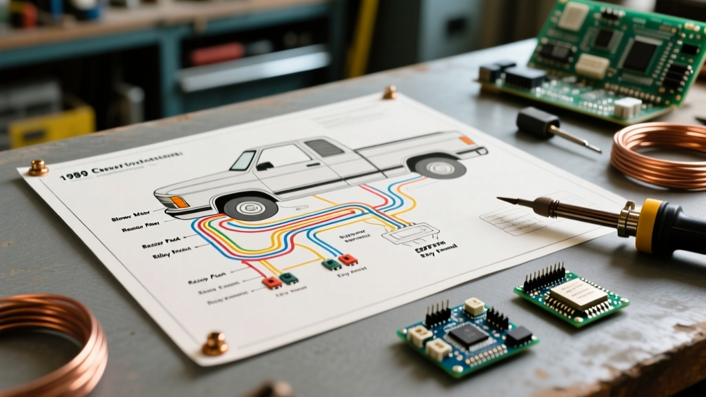
Decoding the Wiring Diagram for 1989 Chevy Truck (C/K Series)
General Motors utilized a highly standardized color-coding and schematic logic system in 1989. When you pull the factory service manual or access archives via the GM Heritage Center, you will notice the schematics treat the HVAC system as a distinct sub-harness branching off the main engine and dash harnesses.
Key Schematic Symbols to Recognize
- Splice Packs (SP): Indicated by a black circle with a number (e.g., SP102). These are physical crimp bundles wrapped in tape, often located under the dash or near the firewall. They are prime locations for hidden corrosion.
- Ground Points (G): Labeled as G100, G200, etc. The blower motor ground is typically tied to the engine block or inner fender apron. A poor ground will cause the blower to back-feed through the AC indicator light on the dash.
- Connectors (C): Labeled with a 'C' followed by a number (e.g., C250). The diagram will show the cavity pinout, which is crucial for multimeter probing.
The Blower Motor Circuit: Step-by-Step Appliance-Style Wiring
To troubleshoot this system like an appliance repair technician, we must map the current flow from the power source, through the user interface (dash switch), into the speed controller (resistor), and finally to the load (blower motor).
| Circuit Function | Factory Wire Color | Wire Gauge | Component Path |
|---|---|---|---|
| Ignition 12V Feed | Purple | 14 AWG | Fuse Panel to HVAC Dash Switch |
| Low/Med/High-Med Feed | Dark Blue | 14 AWG | Dash Switch to Resistor Block |
| Resistor Output to Motor | Light Blue | 14 AWG | Resistor Block to Blower Motor |
| High-Speed Trigger | Yellow | 18 AWG | Dash Switch to High Blower Relay Coil |
| High-Speed Power Feed | Orange | 12 AWG | Junction Block (Fusible Link) to Relay |
| High-Speed Motor Feed | Red | 12 AWG | High Blower Relay to Blower Motor |
| Motor Ground | Black | 12 AWG | Blower Motor Case to Engine Block |
Common Failure Modes & Multimeter Diagnostics
When an HVAC appliance fails, a technician does not immediately replace the motor. They test for voltage drop. In 2026, finding a pristine 1989 harness is nearly impossible. Here are the specific edge cases and failure modes you must test for:
- The Melted Resistor Connector: The 4-pin plug connecting to the resistor block on the passenger side HVAC case frequently melts due to high resistance. Diagnostic: Perform a voltage drop test across the connector while the blower is running on Medium. A reading above 0.2V indicates terminal oxidation requiring a pigtail replacement.
- High-Speed Relay Failure: If the blower works on speeds 1, 2, and 3, but dies on speed 4, the dash switch is likely fine. The issue is usually the high-blow relay located under the hood near the right-side fender, or the 12 AWG Orange wire feeding it has a corroded inline fusible link.
- Dash Switch Back-Feed: If you turn the key off but the blower continues to run on low, or the AC dash light glows dimly when the blower is on, your blower motor ground (Black wire) has failed. The motor is seeking a ground path backward through the dash illumination circuit.
Upgrading the Circuit: The Bosch-Style Relay Bypass
Rather than relying on 37-year-old copper and a fragile dash switch to carry 15+ amps, modern appliance wiring logic dictates moving the heavy current switching to the engine bay. By installing a standard 30A Bosch-style 5-pin automotive relay, you reduce the load on the dash switch to mere milliamps, extending its life indefinitely.
Step-by-Step Relay Upgrade Procedure
- Disconnect the Battery: Always isolate the negative terminal before splicing into the GMT400 dash harness.
- Tap the Trigger Wire: Locate the Yellow wire at the back of the HVAC dash switch. This wire only carries current when the switch is turned to 'High'. Splice a new 18 AWG wire into this Yellow wire and route it through the firewall to the engine bay.
- Wire the Relay Coil (Pins 85 & 86): Connect your new firewall wire to Pin 86 on the relay. Connect Pin 85 to a clean, bare-metal ground on the inner fender.
- Establish Heavy Power (Pin 30): Run a new 10 AWG wire directly from the positive battery terminal (with an inline 30A MAXI fuse installed within 6 inches of the battery) to Pin 30 on the relay.
- Feed the Motor (Pin 87): Run a new 12 AWG wire from Pin 87 directly to the blower motor's power terminal, bypassing the factory Red and Orange wires entirely.
Note: This upgrade only bypasses the High-Speed setting. If you want a fully independent multi-speed appliance setup, you must install a solid-state PWM (Pulse Width Modulation) motor controller, which is highly recommended for modern EV-swapped classic trucks.
Sourcing Authentic GM Schematics
Do not rely on third-party forum scans for critical wire tracing, as colors often fade or are misidentified in photos. For authoritative reference, utilize the GM Heritage Archive to pull original dealer service manual PDFs. Furthermore, understanding standard automotive wire ampacity limits is crucial; referencing SAE International standards (specifically SAE J1128 for low-tension primary cable) ensures your replacement wires can handle the thermal load of the HVAC blower without melting the insulation.
Frequently Asked Questions
Why does my 1989 Chevy blower motor only work on High?
Speeds 1 through 3 route power through the blower motor resistor block. Speed 4 bypasses the resistor entirely via the high-blow relay. If only High works, your resistor block is either burnt out, or the 4-pin connector leading to it has melted and lost continuity.
Can I use a 120V AC home HVAC blower relay in my truck?
No. While the appliance logic is identical, 120V AC relays use different coil windings and contact materials designed for alternating current zero-crossings. Using an AC relay on a 12V DC circuit will result in severe arcing, welded contacts, and a potential engine bay fire.