
The SAE J286 Standard: 7 Pin Wiring Diagram for Trailers
When towing a travel trailer, fifth wheel, or heavy-duty utility rig, the electrical connection between your tow vehicle and trailer is not just a convenience—it is a critical safety system governed by federal law. The NHTSA Federal Motor Vehicle Safety Standards (FMVSS 108) mandate specific lighting and braking visibility requirements for all towed vehicles. To meet these requirements, the recreational vehicle and commercial towing industries rely on the SAE J286 standard, which defines the universal 7 pin wiring diagram for trailers.
Unlike the older 4-pin flat connectors that only support basic tail, brake, and turn signals, the 7-way RV blade connector (often referred to as the Bargman connector) adds dedicated circuits for electric trailer brakes, 12V auxiliary power, and reverse lights. Miswiring this connector or using substandard materials doesn't just result in blown fuses; it can lead to catastrophic brake failure, electrical fires, or DOT compliance violations during commercial inspections.
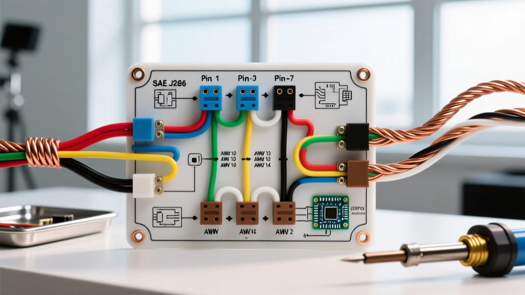
Standard 7-Way RV Pinout Matrix
The following table outlines the industry-standard SAE J286 pinout. Note that while wire colors are standardized, you must always test with a multimeter before splicing, as previous owners or aftermarket shops may have deviated from the code.
| Pin Position | Wire Color | Function | Minimum AWG (Code) |
|---|---|---|---|
| 1 (Top Center) | White | Chassis Ground Return | 10 AWG |
| 2 (Top Right) | Blue | Electric Trailer Brakes | 10 AWG |
| 3 (Bottom Right) | Green | Tail / Running Lights | 12 AWG |
| 4 (Center Right) | Black | 12V Battery Charge / Aux | 10 AWG |
| 5 (Bottom Left) | Red | Left Turn / Stop Lamp | 14 AWG |
| 6 (Top Left) | Brown | Right Turn / Stop Lamp | 14 AWG |
| 7 (Center Pin) | Yellow | Reverse Lights / Aux | 14 AWG |
Wire Gauge Sizing & DOT Voltage Drop Compliance
One of the most frequent safety violations in DIY trailer wiring is undersized conductors. A 12-volt DC system is highly susceptible to voltage drop. According to guidelines derived from the NFPA National Electrical Code (NEC) and marine DC standards, voltage drop on lighting and safety-critical circuits should not exceed 3% (0.36V on a 12V system).
Expert Insight: If your electric brake circuit (Blue wire) experiences a 5% voltage drop due to a long run of undersized 12 AWG wire, your brake magnets will receive only 11.4V. Because brake torque is proportional to the square of the voltage, this seemingly small drop reduces your braking force by nearly 10%, which can be the difference between a safe stop and a jackknife incident on a 6% downgrade.
Recommended Wire Types and Gauges
- Insulation Type: Never use standard PVC building wire (THHN) or cheap automotive primary wire inside trailer conduit. You must use SAE J1128 GXL or SGT wire. GXL features cross-linked polyethylene (XLPE) insulation rated to 125°C, which resists melting when routed near trailer axles and brakes, and won't crack under UV exposure or extreme cold.
- Brake & Power Circuits (Blue, Black, White): Use 10 AWG stranded copper. For trailers exceeding 25 feet in length, bump the Black (12V Aux) and White (Ground) wires to 8 AWG to compensate for the extended round-trip distance and prevent voltage sag when charging trailer house batteries.
- Lighting Circuits (Green, Red, Brown, Yellow): 12 AWG is acceptable for the main harness run, but 14 AWG is sufficient for the final drops to individual LED marker lights.
Grounding Failures: The #1 Safety Violation
Over 70% of all trailer lighting anomalies—such as turn signals backfeeding into the tail lights or dim running lights—are caused by a compromised Pin 1 (White) ground. The FMCSA Vehicle Parts and Accessories Regulations require that all electrical circuits have a dedicated, reliable ground path. Relying solely on the trailer hitch ball and coupler for grounding is a severe safety hazard and a code violation.
Step-by-Step Chassis Grounding Protocol
To ensure a permanent, low-resistance ground path, follow this exact procedure when terminating the White 10 AWG ground wire to the trailer chassis:
- Locate Bare Metal: Identify a section of the main trailer frame rail near the tongue. Do not ground to thin sheet metal, bumper brackets, or the aluminum skin.
- Remove Paint and Rust: Use a 3M Roloc disc or a wire wheel to strip all paint, powder coating, and rust down to bare, shiny steel in a 1-inch diameter circle.
- Apply a Star Washer: Place a stainless steel internal-tooth star washer between the #10 ring terminal and the bare metal. The teeth will bite into the steel to prevent vibration-induced loosening.
- Torque the Bolt: Secure the ring terminal using a Grade 8 hex bolt and a nylon-insert locknut (nyloc). Torque to 15 ft-lbs.
- Seal the Connection: Coat the entire terminal and exposed bare metal with a heavy layer of dielectric grease or fluid film to prevent galvanic corrosion and rust creep, which will eventually increase resistance.
Breakaway Switch & Electric Brake Code Requirements
The Blue wire (Pin 2) does more than just connect to your tow vehicle's brake controller; it is the lifeline to the trailer's breakaway safety system. Federal DOT regulations mandate that any trailer equipped with electric brakes must have a breakaway switch wired to a dedicated, onboard 12V battery.
If the trailer uncouples from the hitch, a physical lanyard pulls the pin from the breakaway switch, closing the circuit and applying full 12V power directly from the breakaway battery to the brake magnets, locking the trailer wheels.
2026 Breakaway Battery Standards
Historically, sealed lead-acid (SLA) batteries were used for breakaway systems. However, as of 2026, safety inspectors and RV manufacturers are heavily favoring 12V LiFePO4 (Lithium Iron Phosphate) breakaway batteries. SLA batteries suffer from severe voltage sag in sub-freezing temperatures, often dropping below the 10.5V threshold required to fully energize the brake magnets. A 5Ah LiFePO4 battery maintains a flat 13.2V discharge curve regardless of ambient temperature, ensuring maximum braking torque during a winter disconnect event. Furthermore, DOT code requires the breakaway battery to have enough capacity to hold the brakes applied for a minimum of 15 minutes.
Weatherproofing & IP67 Connector Standards
Trailers operate in highly corrosive environments, enduring road salt, heavy rain, and high-pressure car washes. Standard vinyl electrical tape and non-insulated crimp connectors will fail within a single season, leading to copper oxidation (green crust) and high-resistance connections.
Mandatory Splicing and Termination Materials
- Adhesive-Lined Heat Shrink: All splices must use dual-wall, polyolefin adhesive-lined heat shrink butt connectors (e.g., Ancor Marine Grade). When heated, the inner wall melts and forms a waterproof, IP67-rated seal that prevents capillary action from drawing water up into the copper strands.
- Corrosion Inhibitors: Spray the finished 7-way plug and socket with a dedicated electrical contact protector like CRC Industries Dielectric Grease or DeoxIT. Never use WD-40, which attracts dust and degrades certain plastic connector housings over time.
- Conduit Routing: All wiring running beneath the trailer must be routed through split loom tubing or flexible PVC conduit, secured with UV-resistant zip ties every 18 inches. Wires must never rest directly on the axle tube or suspension components, where constant vibration will saw through the insulation.
FAQ: Troubleshooting Code Violations & Edge Cases
Why do my trailer tail lights glow dimly when I press the brake pedal?
This is a classic symptom of a high-resistance ground (Pin 1). When the brake circuit demands high current, the electricity seeks an alternative path to ground. It backfeeds through the tail light filament (Pin 3) because the main chassis ground is compromised. Clean and re-torque your white ground wire immediately.
Can I use a 4-pin to 7-pin adapter for a trailer with electric brakes?
No. A 4-pin connector lacks the physical circuits for the Blue (Brakes) and Black (12V Aux) wires. While an adapter will power your lights, your electric brakes will not function, which is a direct violation of FMVSS 108 and a massive liability risk. You must hardwire a 7-way junction box and run a dedicated 10 AWG brake wire to your tow vehicle's brake controller.
My 12V auxiliary pin (Black) isn't charging my trailer battery. Why?
Modern tow vehicles (2020 and newer) often feature a smart tow/haul relay that requires a specific resistance or a CAN-bus handshake to close the 12V auxiliary relay. If the trailer battery is deeply discharged, the tow vehicle's computer may read it as a short circuit and refuse to send power. Ensure your trailer battery is above 11.8V before connecting, and verify the 40-amp inline fuse near the tow vehicle's battery is intact.