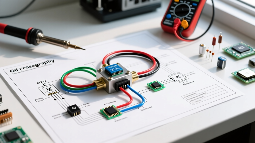

The Critical Role of Oil Pressure Safety Interlocks
When wiring standby generators (like the Generac Guardian 24kW series) or heavy-duty industrial air compressors (such as the Ingersoll Rand SSR-UP5-15), the oil pressure switch is your primary mechanical safeguard against catastrophic bearing failure. As of 2026, with the increased deployment of automated home standby units and off-grid solar backup generators, understanding the exact wiring diagram for oil pressure switch integration is no longer just for industrial mechanics—it is a vital skill for advanced DIYers and appliance technicians.
A properly wired oil pressure switch monitors the engine's lubrication gallery. If pressure drops below a critical threshold (typically 8 to 15 PSI for small air-cooled engines, or 25 to 40 PSI for liquid-cooled diesels), the switch alters its electrical state to either ground the ignition system or cut power to the fuel solenoid, killing the engine before metal-on-metal destruction occurs.
Terminal Configurations Decoded: 1-Pin vs. 2-Pin vs. 3-Pin
Before pulling wire, you must identify your switch type. Using the wrong logic state will result in an engine that either refuses to crank or runs with zero oil pressure. Below is the definitive matrix for common appliance and generator switches.
| Switch Type | Normal State (Engine Off / 0 PSI) | Running State (High PSI) | Primary Application |
|---|---|---|---|
| 1-Terminal (NO) | Closed (Grounds to housing) | Open (Floats) | Small generators, water pumps, basic compressors |
| 2-Terminal (SPST) | Open (Breaks circuit) | Closed (Passes 12V/24V) | Marine diesels, Kohler generators, fuel solenoids |
| 3-Terminal (Dual) | Pins 1-2 Closed, Pins 1-3 Open | Pins 1-2 Open, Pins 1-3 Closed | NFPA 110 Level 1 EPSS systems (Alarm + Shutdown) |
The Fatal DIY Mistake: Direct Wiring vs. Relay Isolation
The most common failure point in aftermarket oil pressure switch wiring is direct connection to the ignition coil. The primary circuit of a standard ignition coil can draw between 3 to 5 amps during operation. However, the internal copper contacts of a standard 1-pin oil pressure switch (like the widely used Generac 079843 or Curtis 1C2048) are typically rated for a maximum of 0.5 amps.
Expert Warning: If you wire a 1-pin switch directly to the ignition coil negative terminal, the high inductive kickback and continuous current will cause micro-arcing inside the switch housing. Within 50 to 100 engine cycles, the internal contacts will weld themselves together in the closed position. When your engine actually loses oil pressure, the switch will fail to ground the coil, resulting in total engine seizure.
The correct wiring diagram for oil pressure switch implementations always utilizes an automotive-style relay to isolate the high-current ignition circuit from the low-current sensor circuit.
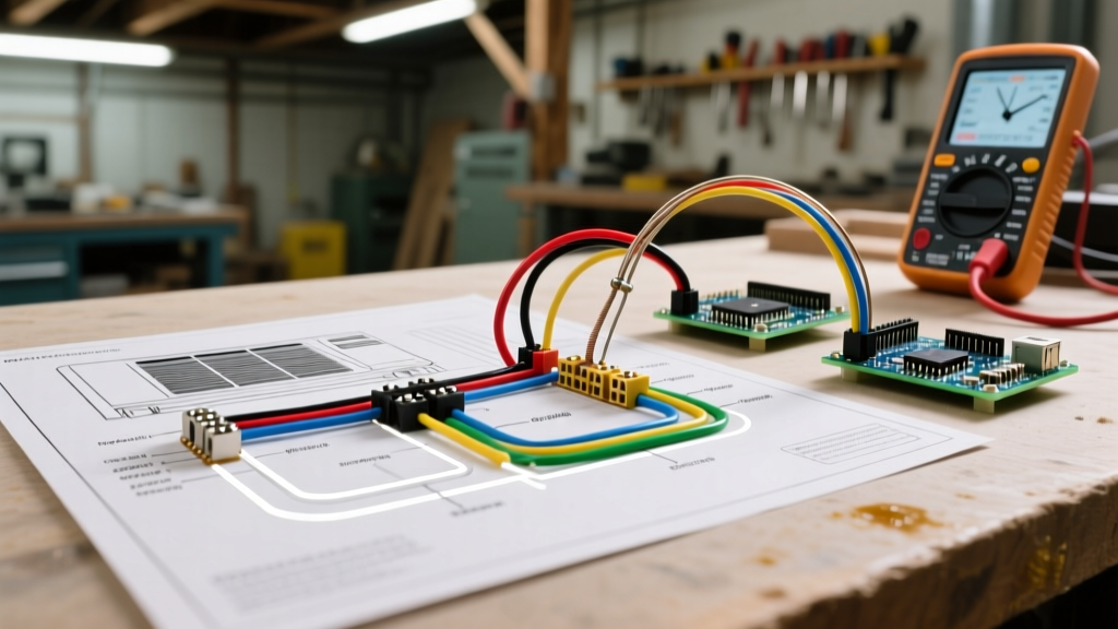
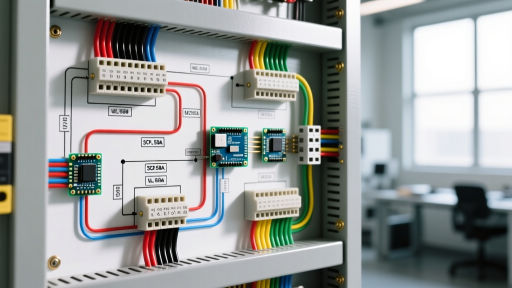
Step-by-Step: Wiring Diagram for Oil Pressure Switch (Single-Pin Grounding)
This guide assumes a 12VDC system using a Normally Open (NO) 1-pin switch that closes to ground upon low oil pressure. We will use a standard Bosch-style 5-pin relay (e.g., Bosch 0332014150, approx. $12.50) to handle the heavy lifting.
Phase 1: Component Preparation
- Wire Selection: Use 16 AWG TXL or SXL cross-linked polyethylene wire. Avoid standard THHN building wire, as it cannot withstand the 105°C+ ambient temperatures near an engine block. (Cost: ~$0.85/ft for premium marine-grade tinned copper).
- Connector Selection: Discard standard vinyl slip-on spade connectors. Engine vibration will shake them loose, causing false shutdowns. Use nylon-insulated, heat-shrink locking ring terminals (e.g., 3M Highland 4094 series) or Deutsch DT series connectors for the switch interface.
- Mounting: Secure the relay in a weatherproof fuse box enclosure (like the Blue Sea Systems 5025, ~$45.00) mounted away from direct exhaust heat.
Phase 2: The Wiring Sequence
- Relay Pin 86 (Coil +): Connect to a switched 12V source that is only live when the ignition key or start toggle is in the "RUN" position.
- Relay Pin 85 (Coil -): Route a 16 AWG wire directly to the single terminal on the oil pressure switch. (The switch body grounds through the engine block).
- Relay Pin 30 (Common): Connect to a clean, bare-metal chassis ground. Verify continuity to the battery negative terminal (must read less than 0.2 ohms).
- Relay Pin 87 (Normally Open): Connect to the negative terminal of the ignition coil (or the ECU "Kill" pin on modern fuel-injected appliances).
- Relay Pin 87a (Normally Closed): Leave this terminal empty and insulated. It is not used in this specific safety logic.
Phase 3: Logic Verification
When the engine is running, oil pressure is high. The switch is OPEN. The relay coil receives no ground, so the relay remains OFF. Pin 30 and Pin 87 are disconnected. The ignition coil fires normally.
If oil pressure drops, the switch CLOSES to ground. The relay coil energizes. Pin 30 connects to Pin 87. The ignition coil negative is instantly grounded, killing the spark and shutting down the appliance safely.
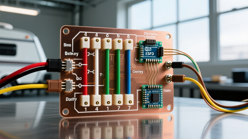
Advanced 3-Terminal Murphy Switch Integration
For commercial standby generators and industrial compressors, a simple shutdown is insufficient; operators require a pre-alarm. The Murphy P128L series and similar 3-terminal switches provide a dual-circuit solution.
In this configuration, Terminal 1 is the common feed (12V). Terminal 2 connects to a dashboard warning light or SCADA alarm input (triggered when pressure drops below 20 PSI). Terminal 3 connects to the shutdown relay (triggered only if pressure drops below 10 PSI). This tiered response is heavily favored in modern facility management to prevent nuisance outages during cold-weather startups when oil viscosity is high and pressure spikes momentarily.
Troubleshooting Edge Cases & False Trips
If your generator or compressor is shutting down randomly despite full oil levels, diagnose these specific edge cases before replacing the switch:
- The Ground Loop Trap: If the engine block has poor grounding to the main chassis (common in rusted compressor skids or generator enclosures with rubber vibration isolators), the switch cannot complete the circuit to the relay. Fix: Run a dedicated 10 AWG ground strap from the engine block to the chassis ground bus.
- Moisture Ingress: Pressure washing an appliance enclosure can force water past the switch's rubber boot. This creates a temporary conductive path to ground, mimicking a low-pressure event. Fix: Coat all spade connections in liquid electrical tape (e.g., Star brite 090608) rather than relying on standard vinyl electrical tape, which peels under thermal cycling.
- Gauge Sender Interference: Never wire an analog oil pressure gauge sender in series with a safety shutdown switch. The varying resistance of the gauge will alter the voltage reaching the relay coil, causing erratic relay chatter. Always use a dedicated switch port on the engine block or a manifold tee fitting.
Code Compliance and Safety Standards
When wiring oil pressure safety interlocks for residential or commercial standby generators, you must adhere to local electrical codes and national standards. According to NFPA 110 (Standard for Emergency and Standby Power Systems), Level 1 EPSS (Emergency Power Supply Systems) require automatic shutdown for low oil pressure, but also mandate that audible and visual alarms be triggered prior to the shutdown threshold to allow for manual intervention or safe load shedding.
Furthermore, always consult the specific manufacturer's wiring schematics for your exact appliance model. Modern 2026 brushless alternator controllers often feature solid-state ECU inputs that expect a 5V logic signal rather than a direct 12V ground; feeding 12V into a 5V logic pin via a miswired relay will instantly destroy the engine control module, resulting in a $1,200+ replacement cost.
Final Verification Checklist
Before putting the appliance into automatic service mode, perform this bench test:
- Disconnect the wire from the oil pressure switch terminal.
- Turn the ignition to "RUN" (do not crank the engine).
- Manually ground the disconnected wire to the engine block for 1 second.
- You should hear an audible "click" from the isolation relay, and the ignition spark/fuel solenoid should immediately deactivate.
- Remove the ground; the system should reset instantly.
By isolating the sensor circuit from the high-current ignition loads and utilizing proper environmental sealing, your oil pressure switch wiring will provide decades of reliable, fail-safe engine protection.