
Mastering the Single Electric Fan Wiring Diagram for PSC Motors
Wiring a single-phase alternating current (AC) fan motor requires precision, an understanding of electromagnetic principles, and strict adherence to electrical codes. Whether you are replacing a blower motor in a residential HVAC air handler or wiring an industrial exhaust fan, the single electric fan wiring diagram is your primary roadmap. In 2026, the vast majority of single-phase fractional horsepower fan applications utilize the Permanent Split Capacitor (PSC) motor due to its high reliability, quiet operation, and excellent multi-speed capabilities.
This comprehensive motor wiring tutorial dissects the PSC architecture, decodes standard manufacturer diagrams, and provides actionable, step-by-step installation protocols. We will cover exact terminal identifications, capacitor sizing matrices, and critical failure modes that generic guides often overlook.
Anatomy of the PSC Fan Motor
Before interpreting any single electric fan wiring diagram, you must understand the internal architecture of the PSC motor. Unlike Capacitor-Start/Capacitor-Run (CSCR) motors, a PSC motor lacks a centrifugal switch. Instead, it uses a run capacitor that remains in the circuit continuously during operation.
- Main (Run) Winding: Constructed with thicker wire and lower resistance, this winding provides the primary magnetic field and handles the bulk of the continuous operating current.
- Auxiliary (Start) Winding: Made with thinner wire and higher resistance, this winding is connected in series with the run capacitor. It creates a phase shift in the alternating current, generating the rotating magnetic field necessary to produce starting torque.
- Run Capacitor: Typically an oil-filled or metallized polypropylene film cylinder rated between 3 MFD and 15 MFD (microfarads) at 370VAC or 440VAC. It optimizes the phase angle for maximum efficiency at running speed.
- Thermal Overload Protector (TOP): An internally mounted bimetallic strip that breaks the circuit if the motor winding temperature exceeds safe limits (usually around 250°F / 121°C), automatically resetting once cooled.
Decoding the Single Electric Fan Wiring Diagram
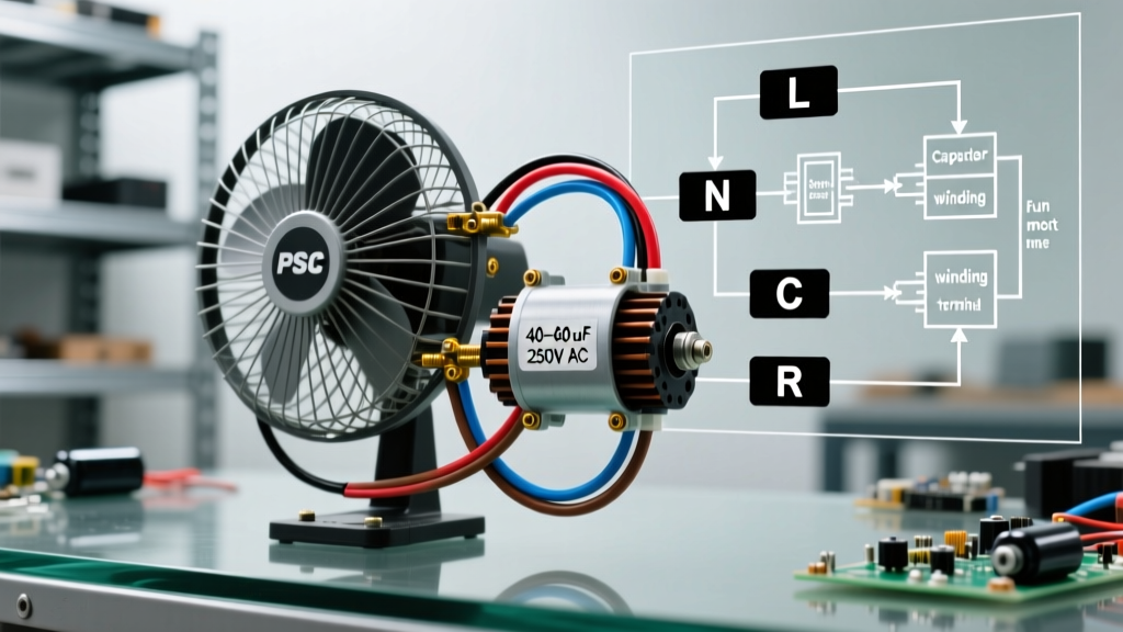
Manufacturer diagrams for PSC motors (such as those found on Fasco, Dayton, or Century motor nameplates) generally feature a 3-wire or 4-wire configuration for multi-speed setups. Understanding the standard NEMA (National Electrical Manufacturers Association) color coding and terminal designations is critical.
Standard 4-Wire Multi-Speed Configuration
Most modern HVAC blower motors utilize a 4-wire setup to allow for High, Medium, and Low speeds. According to Penn State Extension's electrical motor guidelines, proper identification of these leads prevents catastrophic winding burnout.
- Line 1 (L1) / Hot: Connects to the main power source (typically 120V or 240V). This feeds the common junction of the windings.
- Neutral (L2): Connects to the speed taps. You will only connect ONE speed tap at a time. The unused speed taps must be individually insulated and tied off; never wire them together or to ground.
- Capacitor Lead 1 (Usually Brown): Connects to one terminal of the run capacitor.
- Capacitor Lead 2 (Usually Brown with White Stripe): Connects to the opposite terminal of the run capacitor.
Expert Warning: Never apply power to a PSC motor without the run capacitor connected. Doing so will cause the auxiliary winding to overheat rapidly, as it is not designed to carry continuous current without the impedance provided by the capacitor. This is a leading cause of warranty voids on replacement motors like the Dayton 1TDP7 series.
Step-by-Step Wiring Procedure
Proper execution of the single electric fan wiring diagram requires the right tools and techniques. In 2026, the average cost of a replacement 1/2 HP PSC motor ranges from $110 to $180, making careful installation essential to protect your investment.
1. Preparation and Lockout/Tagout (LOTO)
Always disconnect power at the main breaker panel and apply a physical lockout device. Verify the absence of voltage using a CAT III or CAT IV rated multimeter (such as the Fluke 117, priced around $220). Test from Line to Neutral, Line to Ground, and Neutral to Ground to ensure no phantom voltages or back-feeds exist.
2. Wire Stripping and Termination
Do not wrap bare wire around screw terminals on contactors or terminal blocks. Use fully insulated female spade disconnects. For 14 AWG THHN wire (standard for 15A motor circuits), use a precision wire stripper to remove exactly 3/4 inch of insulation. Crimp the terminal using a ratcheting crimper (e.g., Klein Tools 1005) to ensure a gas-tight connection that will not vibrate loose under the motor's operational harmonics.
3. Capacitor Wiring and Torque Specifications
Connect the brown and brown/white leads to the run capacitor. The polarity of a standard AC run capacitor does not matter (the terminals are usually marked 'C' and 'FAN' or 'HERM', but for a single fan capacitor, either leg works). When tightening the 1/4-inch spade connectors onto the capacitor blades, use a nut driver and apply exactly 12 to 15 inch-pounds of torque. Overtightening can crack the internal seal, leading to dielectric fluid leaks and premature capacitor failure.
Capacitor Sizing and Selection Matrix
Selecting the correct run capacitor is paramount. A capacitance value that is too high will overheat the auxiliary winding; a value that is too low will result in weak starting torque and excessive slip. Refer to the motor nameplate for the exact MFD (or µF) requirement. If the nameplate is illegible, use the matrix below as a baseline reference for standard 120V/240V PSC fan motors, corroborated by the US Department of Energy's Motor Sizing Guide.
| Motor HP | Voltage | Typical MFD (µF) | Voltage Rating | 2026 Avg. Price |
|---|---|---|---|---|
| 1/4 HP | 120V / 240V | 3 to 5 MFD | 370VAC | $8 - $12 |
| 1/3 HP | 120V / 240V | 5 to 7.5 MFD | 370VAC | $10 - $14 |
| 1/2 HP | 240V | 7.5 to 10 MFD | 370VAC / 440VAC | $12 - $18 |
| 3/4 HP | 240V | 10 to 15 MFD | 440VAC | $15 - $22 |
Real-World Troubleshooting and Edge Cases
Even when you follow the single electric fan wiring diagram perfectly, field conditions can introduce variables that cause operational failures. Here are advanced troubleshooting protocols for common PSC motor issues.
Motor Hums but Fails to Start
Diagnosis: This is the classic symptom of a failed run capacitor or a mechanical bind. Action: First, safely discharge the capacitor using a 20,000-ohm, 5-watt resistor (never use a screwdriver, as the resulting arc will pit the capacitor blades and create a high-resistance hotspot). Test the capacitance with a dedicated meter like the Fieldpiece SC260. If the reading is more than 6% below the rated MFD, replace it. If the capacitor tests fine, check the fan blade for physical obstruction or seized sleeve bearings.
Motor Overheats and Cycles on Internal Overload
Diagnosis: Incorrect voltage tap selection, poor ventilation, or excessive static pressure in the ductwork. Action: Verify that the applied voltage is within 10% of the nameplate rating. If you wired the motor to the 'High' speed tap but the application requires high torque at low RPM, the motor will draw excessive Locked Rotor Amps (LRA) and trip the TOP. Re-wire to the appropriate speed tap and use an anemometer to verify airflow is not restricted by dirty filters or collapsed flex duct.
Unused Speed Taps Inducing Phantom Voltage
Diagnosis: In multi-speed PSC motors, the unused windings act as autotransformers. If the bare ends of unused speed wires are touching each other or the grounded chassis, they will induce a short circuit through magnetic induction, instantly destroying the motor. Action: Always terminate unused speed wires with individual closed-end wire connectors (wire nuts) and secure them away from the motor housing and the capacitor.
Safety, Grounding, and NEC Compliance
All motor installations must comply with the National Electrical Code (NEC), specifically Article 430, which governs Motors, Motor Controllers, and Motor Control Centers. For single electric fan wiring, proper equipment grounding is non-negotiable. The motor casing must be bonded to the equipment grounding conductor (EGC) using a green grounding screw or a dedicated grounding clip. This ensures that in the event of an internal winding short to the casing, the fault current will immediately trip the branch circuit breaker, preventing lethal shock hazards.
Furthermore, when working on commercial or industrial fan arrays, adhere strictly to OSHA electrical safety standards regarding arc flash boundaries and personal protective equipment (PPE). Even fractional horsepower motors can generate significant arc flash energy if a dead short occurs at the terminal block while the circuit is energized.
Final Verification Protocol
Once the single electric fan wiring diagram has been executed and all physical connections are verified, perform a final pre-flight check before energizing:
- Verify all terminal screws are torqued to spec.
- Ensure the run capacitor is securely strapped in an upright position to prevent internal oil pooling away from the dielectric film.
- Confirm the fan blade spins freely by hand with zero lateral play.
- Stand clear of the blade path, remove LOTO devices, and apply power.
Measure the running amperage with a clamp meter. The reading should be at or slightly below the Full Load Amps (FLA) listed on the nameplate. If the amperage is significantly higher, immediately cut power and re-evaluate the mechanical load and wiring configuration.