
Understanding the 7-Way RV Blade Standard
When towing travel trailers, fifth wheels, or heavy utility trailers equipped with electric brakes, the 7-way RV blade connector is the undisputed industry standard. Unlike the simpler 4-way flat connector used for light-duty utility trailers, the 7-way configuration provides dedicated circuits for electric brakes, a 12V auxiliary power feed for charging trailer batteries, and an auxiliary pin for reverse lights or hydraulic brake lockouts. In 2026, with the widespread adoption of advanced proportional Bluetooth brake controllers like the Curt Echo and REDARC Tow-Pro Elite, ensuring your wiring harness can handle modern electrical loads is more critical than ever.
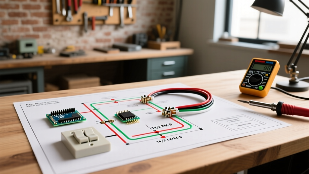
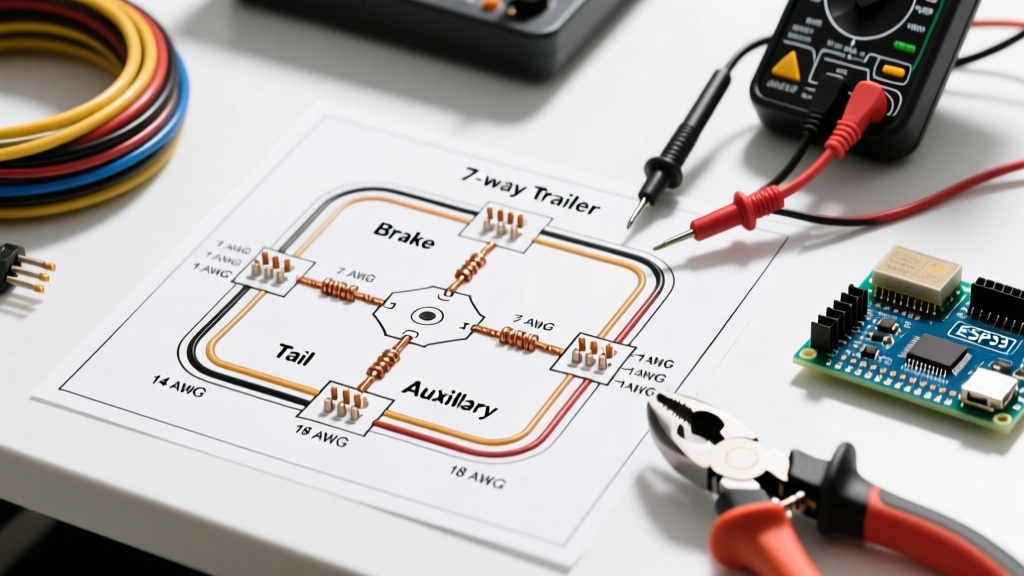
This comprehensive guide breaks down the exact specifications, wire gauge requirements, and failure modes associated with the standard 7-way setup. Whether you are building a custom harness from scratch or diagnosing a faulty connection, referencing an accurate trailer electric wiring diagram is the first step toward a safe and compliant tow rig.
The Complete 7-Way Trailer Pinout Matrix
The physical layout of the 7-way connector follows a strict clock-face orientation established by the RV Industry Association (RVIA). When looking at the socket on the tow vehicle (the female end), the pins are arranged as follows:
| Pin Position | Wire Color | Function | Minimum AWG (up to 25ft) | Typical Amperage |
|---|---|---|---|---|
| 7 o'clock (Bottom) | White | System Ground | 10 AWG | 30A+ (Combined) |
| 5 o'clock | Blue | Electric Brakes | 10 AWG | 10A - 15A |
| 1 o'clock | Green | Tail / Running Lights | 14 AWG | 2A - 5A |
| 11 o'clock | Black | 12V Aux / Battery Charge | 10 AWG | 15A - 30A |
| 9 o'clock | Red | Left Turn / Stop | 14 AWG | 4A - 8A |
| 3 o'clock | Brown | Right Turn / Stop | 14 AWG | 4A - 8A |
| Center | Yellow | Auxiliary / Reverse Lights | 14 AWG | 5A - 10A |
Pro Tip: Never rely solely on wire color when diagnosing an existing trailer. Previous owners frequently use whatever wire is available for repairs. Always use a digital multimeter or a dedicated circuit tester (like the Hopkins 40376) to verify pin function before splicing into a new harness.
Wire Gauge Selection: Beating Voltage Drop
One of the most common mistakes DIYers make when building a trailer harness is undersizing the wire to save money. With copper prices remaining elevated in 2026, 10 AWG primary wire costs roughly $0.75 to $1.10 per foot, compared to $0.40 for 14 AWG. However, skimping on wire gauge for high-draw circuits leads to severe voltage drop, which directly compromises safety.
The Math Behind the Brakes
Electric trailer brakes typically draw between 3 to 4 amps per axle. A triple-axle toy hauler will pull up to 12 amps when the brake controller commands maximum stopping power. If you use 12 AWG wire for a 30-foot run from the tow vehicle's controller to the trailer's breakaway switch and brake magnets, you will experience a voltage drop of approximately 1.2 volts. This means your brake magnets are only receiving 10.8 volts instead of the full 12 volts, resulting in noticeably weaker braking performance and causing modern proportional controllers to falsely report an 'Overload' (OL) or 'Short Circuit' (SC) error.
- 10 AWG Wire: Mandatory for the Ground (White), Electric Brakes (Blue), and 12V Aux (Black) circuits. Handles up to 30 amps with minimal voltage drop over standard trailer lengths.
- 12 AWG Wire: Acceptable for lighting circuits on larger fifth wheels where the run from the junction box to the rear lights exceeds 35 feet.
- 14 AWG Wire: Perfectly adequate for Turn/Stop (Red/Brown), Tail (Green), and Aux (Yellow) circuits on trailers under 25 feet in length.
Step-by-Step Wiring and Crimping Protocol
A wiring diagram is only as good as the physical connections it relies on. The harsh environment under a trailer—exposed to road salt, vibration, and extreme temperature swings—demands marine-grade termination techniques.
- Strip the Jacket: Use a precision wire stripper (such as the Wirefy heavy-duty automatic stripper) to remove exactly 3/8 inch of insulation. Avoid nicking the copper strands, which creates a weak point prone to snapping under vibration.
- Crimp the Terminal: Use insulated ring terminals sized specifically for your wire gauge (e.g., 10-12 AWG #10 ring terminal). Use a ratcheting crimping tool to ensure a gas-tight mechanical bond. A proper crimp should require over 40 lbs of pull force to separate.
- Seal with Heat Shrink: Slide adhesive-lined, marine-grade heat shrink tubing (such as Ancor 3/16 inch) over the connection. Apply heat evenly until the adhesive oozes slightly from the ends. This creates a waterproof seal that prevents galvanic corrosion inside the copper strands.
- Route and Protect: Run all wiring through flexible split loom tubing. Secure the loom to the trailer frame every 18 inches using UV-resistant nylon zip ties or stainless steel P-clips. Never route wiring near exhaust components or moving suspension parts.
Upgrading from a 4-Way Flat to a 7-Way Blade
If your tow vehicle currently has a 4-way flat connector and you are upgrading to a camper with electric brakes, you have two options:
Option A: The Adapter Route (Temporary/Light Duty)
You can use a molded adapter like the Hopkins 47185 (4-way flat to 7-way blade). However, this only adapts the lighting circuits. You will still need to run a separate heavy-duty 10 AWG blue wire from a dedicated brake controller in your cab directly to the 7-way socket, and a separate 10 AWG white wire to a clean, bare-metal ground on the vehicle frame. This results in a messy, dangling setup that is prone to snagging.
Option B: Hardwiring a 7-Way Socket (Recommended)
The professional approach is to remove the 4-way flat entirely and hardwire a dedicated 7-way socket (such as the Pollak PK11720) into your vehicle's wiring harness. You will splice the green, brown, yellow, and red wires into your vehicle's existing tail and turn signal circuits using heat-shrink butt connectors. The blue wire routes directly to the output pin of your aftermarket brake controller, and the black wire connects to the vehicle battery via a 30-amp inline circuit breaker. This provides a clean, factory-looking installation that eliminates adapter failure points.
Advanced Troubleshooting: Beyond the Basics
Even with a perfect trailer electric wiring diagram, environmental factors will eventually cause issues. Here is how to diagnose the three most common 7-way failure modes:
1. The Phantom Ground Backfeed (Pin 1 Failure)
Symptom: When you press the brake pedal, the trailer's running lights illuminate, or the turn signals flash rapidly and dimly.
Diagnosis: The white ground wire has failed, usually due to corrosion at the vehicle frame attachment point. Because the circuit cannot complete through the ground pin, the electrical current seeks an alternative path to ground, backfeeding through the tail light circuit. Fix: Sand the vehicle frame down to bare metal, apply dielectric grease to the ring terminal, and secure it with a star washer and stainless steel bolt.
2. Brake Controller 'OL' Error (Pin 2 Resistance)
Symptom: The in-cab brake controller displays an Overload or Short Circuit error, and the trailer brakes do not engage.
Diagnosis: There is high resistance or a dead short in the blue brake wire. This is frequently caused by the blue wire chafing against the trailer's steel A-frame near the coupler, or by moisture ingress inside the breakaway switch. Fix: Disconnect the trailer. Use a multimeter to check continuity between the blue pin on the trailer plug and the trailer frame. If you read continuity (near zero ohms), you have a short to ground. Inspect the A-frame routing and the breakaway switch for physical damage.
3. Intermittent 12V Aux Power Loss (Pin 4 Voltage Drop)
Symptom: The trailer's interior 12V appliances shut off while driving, or the trailer battery fails to charge despite being plugged in.
Diagnosis: The black 12V auxiliary wire is undersized, or the tow vehicle's factory tow package relay is failing to pass adequate current. Many modern trucks use a smart alternator that drops system voltage to 12.8V under light loads. If your wire gauge is too small, the voltage at the trailer battery drops below the 12.2V threshold required to initiate charging. Fix: Upgrade the black wire to 8 AWG if the run exceeds 20 feet, and verify that the tow vehicle's factory trailer charge relay is fully seated and rated for at least 30 amps.
Regulatory Compliance and Safety Standards
When modifying or building trailer lighting and braking circuits, your setup must comply with federal safety regulations. In the United States, all trailer lighting must meet the visibility and performance requirements outlined in Federal Motor Vehicle Safety Standard (FMVSS) 108, enforced by the National Highway Traffic Safety Administration (NHTSA). This standard dictates minimum candela output for stop lamps, turn signals, and side marker lights, which directly impacts how many fixtures you can wire to a single circuit before overloading the wiring.
Furthermore, the physical connector layout and pin assignments are governed by RV Industry Association (RVIA) standards and SAE J286. Adhering strictly to the color codes and pinouts detailed in this guide ensures that your trailer will interface safely with any compliant tow vehicle on the road, preventing catastrophic cross-wiring scenarios that could lock up your trailer brakes at highway speeds.