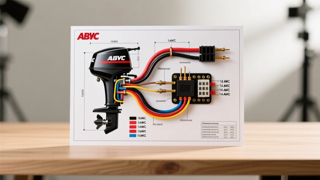

The Critical Role of ABYC Standards in Marine Electrical Systems
When interpreting or creating a wiring diagram for outboard motor applications, relying on standard automotive electrical knowledge is a recipe for catastrophic failure. Marine environments subject electrical systems to constant vibration, high humidity, saltwater corrosion, and extreme temperature fluctuations. To combat these elements, the American Boat & Yacht Council (ABYC) established the E-11 standard, which dictates strict requirements for marine wire gauge sizing, color coding, and insulation types.
As of 2026, modern outboard engines—particularly high-horsepower four-strokes and electric-start models with integrated digital network gauges—rely on highly sensitive Engine Control Units (ECUs). A voltage drop of just 0.5 volts during cranking can cause an ECU reset, leaving you stranded. This guide provides a comprehensive reference for ABYC color codes, wire gauge selection matrices, and the nuances of translating OEM schematics into physical marine-grade wiring.
Master ABYC Color Code Chart for Outboard Motors
Unlike household wiring (NEC) or automotive standards (SAE), marine DC electrical systems utilize a specific color palette to prevent dangerous cross-connections. Below is the definitive ABYC E-11 color code reference for 12V and 24V outboard motor systems.
| Wire Color | ABYC Designation | Typical Outboard Application |
|---|---|---|
| Red | DC Positive (Main) | Starter motor positive, main battery feed to ignition switch, alternator output. |
| Yellow or Yellow/Black | DC Negative (Ground) | Main battery ground to engine block, ECU ground, starter motor negative. |
| Purple | Ignition Switch | Power from ignition switch to engine harness, ECU wake-up signal, choke circuits. |
| Dark Blue | Navigation Lights | Running lights, anchor light feeds (rarely used inside the cowling, common at helm). |
| Light Blue | Oil Pressure | Oil pressure switch signal to helm warning gauge or ECU alarm input. |
| Gray | Tachometer | Signal wire from alternator rectifier to the helm tachometer gauge. |
| Pink | Fuel Sender | Signal from the fuel tank sender unit to the helm fuel gauge. |
| Green or Green/Yellow | DC Bonding / Grounding | Engine block bonding to the transom zinc or common grounding bus bar. |
| Brown | Lighting / Accessories | Bilge pump feeds, courtesy lights, or secondary accessory circuits. |
The OEM Discrepancy: Japanese vs. US Color Codes
One of the most common pitfalls when reading a wiring diagram for outboard motor systems manufactured by Japanese OEMs (such as Yamaha, Suzuki, or Honda) is the internal harness color coding. Inside the sealed engine cowling, Japanese manufacturers often use Black for DC ground and White or Red for positive feeds, adhering to JIS (Japanese Industrial Standards). However, the moment that harness connects to the main marine plug (the rigging cable running to the helm), it must transition to ABYC colors (Yellow for ground, Red for positive). Always verify whether your schematic depicts the internal engine harness or the external marine rigging harness before cutting or splicing wires.
Wire Gauge Selection Matrix & Voltage Drop Rules
Selecting the correct wire gauge is not merely about preventing the wire from melting; it is about managing voltage drop. According to ABYC standards, critical electronics (ECUs, GPS, navigation lights) must not experience a voltage drop exceeding 3% of the system voltage (0.36V on a 12V system). Non-critical loads (cabin lights, baitwell pumps) can tolerate up to a 10% drop.
The following matrix assumes a 12V DC system using UL 1426 marine-grade tinned copper wire at an ambient temperature of 104°F (40°C).
| Wire Gauge (AWG) | Max Ampacity (ABYC) | Max Distance for 15A (3% Drop) | Common Outboard Application |
|---|---|---|---|
| 16 AWG | 10 Amps | Not recommended for 15A | Instrument illumination, ECU sensor signals. |
| 14 AWG | 15 Amps | 12 feet | Horn, trim/tilt relay control circuits, lighting. |
| 12 AWG | 20 Amps | 20 feet | Fuel pumps, bilge pumps, accessory sockets. |
| 10 AWG | 30 Amps | 32 feet | Trim/tilt motor power feeds, heavy accessories. |
| 6 AWG | 60 Amps | 15 feet (at 40A) | Alternator main charge lines to battery bank. |
| 1/0 AWG | 150 Amps | 10 feet (at 120A) | Main starter motor positive and negative cables. |
| 2/0 AWG | 175 Amps | 15 feet (at 120A) | Long-run starter cables, main battery interconnects. |
Expert Insight: Never use Copper Clad Aluminum (CCA) wire for marine applications. While CCA wire is up to 40% cheaper than pure copper, it has significantly higher resistance, is highly susceptible to galvanic corrosion when crimped to copper terminals, and is strictly prohibited by ABYC E-11 standards. Always look for the UL 1426 stamp on the wire jacket.
Real-World Failure Modes and Edge Cases
Even with a perfect wiring diagram for your outboard motor, physical installation errors can lead to intermittent and frustrating failures. Here are three edge cases that frequently stump marine technicians:
1. Capillary Action and 'Black Wire' Disease
If you use untinned automotive wire (SAE J1128) in a saltwater environment, saltwater can wick up the copper strands via capillary action if the wire end is exposed. This causes the copper to oxidize and turn black deep inside the insulation—a phenomenon known as 'black wire disease.' The wire becomes brittle and increases resistance. Marine-grade tinned copper wire prevents this by coating each individual strand in tin, sealing the copper from oxygen and moisture.
2. Starter Motor Voltage Drop Causing ECU Resets
Modern 4-stroke outboards draw massive current (often 120A to 150A) during the initial cranking phase. If the 1/0 AWG battery cables are routed over long distances (e.g., from a forward console battery bank to a transom-mounted motor), the voltage at the ECU can drop below 9V. This triggers an automatic ECU shutdown to protect the processor, resulting in a 'dead crank' where the starter turns but the engine refuses to fire. The fix is upsizing to 2/0 AWG or relocating a dedicated cranking battery within 5 feet of the engine.
3. Vibration Fatigue at Crimp Joints
Outboard engines generate high-frequency harmonic vibrations. Standard vinyl-insulated crimp connectors will eventually fatigue and snap at the crimp barrel. Marine electricians exclusively use adhesive-lined polyolefin heat shrink terminals (such as 3M EPS300). When heated, the inner adhesive melts and flows into the wire strands, creating a waterproof, gas-tight seal that physically locks the wire into the terminal, eliminating vibration fatigue.
Step-by-Step Protocol for Tracing and Rewiring
When troubleshooting or replacing a harness based on your outboard motor wiring diagram, follow this systematic protocol to ensure safety and compliance:
- Disconnect and Isolate: Always disconnect the negative (Yellow/Black) battery cable first. Tape the terminal to prevent accidental reconnection while working inside the cowling.
- Verify the Schematic Legend: Check the title block of your OEM wiring diagram. Confirm if the colors listed represent the internal engine harness (JIS) or the external rigging harness (ABYC).
- Perform a Voltage Drop Test: Before replacing wires, use a digital multimeter to measure voltage drop across the positive and negative circuits while the engine is cranking. A reading over 0.3V on a 12V system indicates undersized wire or corroded terminals.
- Strip and Crimp: Use a precision wire stripper to avoid nicking the tinned strands. Use a ratcheting crimper calibrated for marine heat-shrink terminals to ensure a uniform, gas-tight compression.
- Seal and Secure: Apply heat to the adhesive-lined terminals until the adhesive purges slightly from the edges. Secure the wire runs using UV-resistant nylon cable ties and edge protectors where the harness passes through aluminum bulkheads or fiberglass rigging tubes.
Conclusion
Successfully executing a wiring diagram for outboard motor systems requires more than just connecting positive to positive and negative to negative. It demands a strict adherence to ABYC color codes, precise wire gauge calculations based on run length and amperage, and the exclusive use of UL 1426 tinned marine wire. By understanding the discrepancies between OEM internal schematics and US marine standards, and by utilizing proper adhesive-lined crimping techniques, you ensure your vessel's electrical system remains reliable, safe, and compliant with NMMA and ABYC standards for years to come.