
The Critical Difference: Schematics vs. Wiring Diagrams
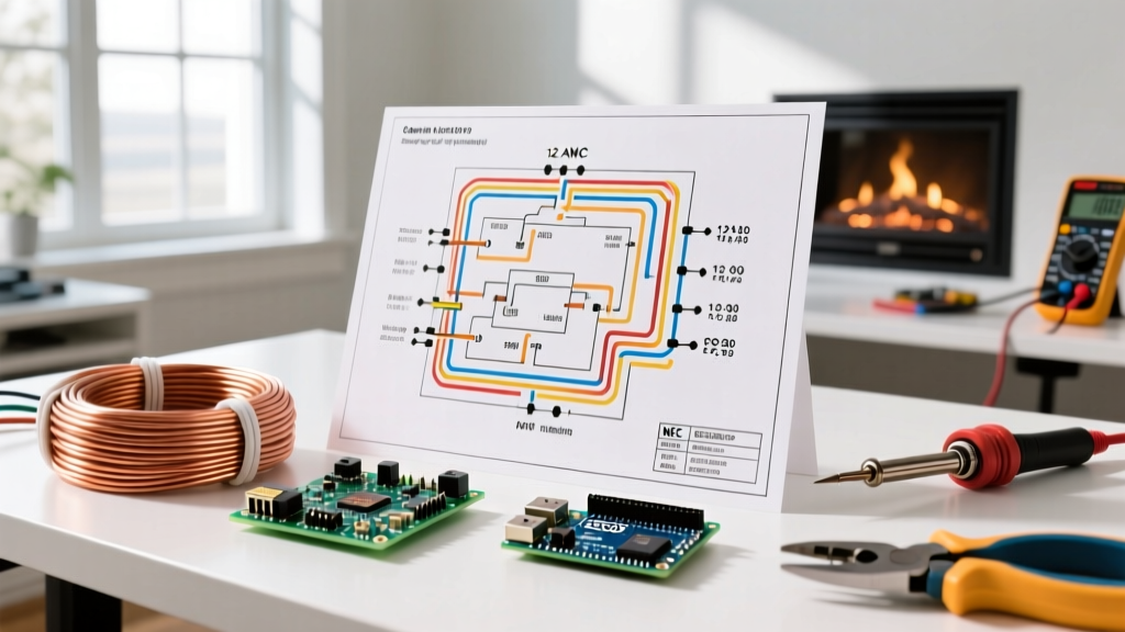
Before grabbing your wire strippers, it is vital to understand what you are looking at. Many DIYers and even junior technicians confuse electrical schematics with wiring diagrams. A schematic shows the logical flow of a circuit using standardized symbols, ignoring the physical layout. An electric wiring diagram, however, is a physical roadmap. It illustrates exactly where wires route, which terminals they land on, and how components are physically arranged in the enclosure. When you are executing a step-by-step wiring walkthrough, the wiring diagram is your primary source of truth for physical connections.
Phase 1: Decoding the Electric Wiring Diagram Legend
Every professional diagram includes a legend. Misinterpreting a single symbol—like confusing a Normally Open (NO) contact with a Normally Closed (NC) contact—will result in a dead short or a malfunctioning control circuit. Below is a reference table for the most common symbols you will encounter in residential and light commercial 240V diagrams.
| Symbol / Abbreviation | Component Name | Physical Meaning in the Panel |
|---|---|---|
| L1, L2 | Line Voltage Legs | The two 120V hot legs from a split-phase panel, yielding 240V across them. |
| N / Neutral | Neutral Bus | The grounded conductor. Usually white or gray. Carries unbalanced current. |
| GND / PE | Equipment Ground | Bare copper or green. Connects to the chassis for fault clearing. Never carries normal current. |
| NO | Normally Open | Contacts that remain open (no continuity) until the relay or contactor coil is energized. |
| NC | Normally Closed | Contacts that maintain continuity until the coil is energized, breaking the circuit. |
Phase 2: Pre-Wiring Preparation and Safety Protocols
Working with 240V circuits leaves zero margin for error. According to OSHA's Control of Hazardous Energy (LOTO) standards, simply flipping a breaker is not enough; you must physically lock out the panel and verify the absence of voltage.
Required Tool Loadout
- Voltage Tester: Fluke 117 True RMS Multimeter or Fluke 1AC-II VoltAlert. Never trust a cheap non-contact pen tester for life-safety verification.
- Wire Strippers: Klein Tools 11063W (for 10-14 AWG solid/stranded). Clean strips prevent nicking the copper, which creates hot spots.
- Torque Screwdriver: Wiha 28501 or similar, calibrated to inch-pounds. The National Fire Protection Association (NFPA) mandates specific torque values for breaker terminals in recent NEC cycles to prevent loose connections and arc faults.
- Wire: 10 AWG THHN Copper (rated for 30A circuits, standard for water heaters and HVAC compressors).
Phase 3: Step-by-Step Walkthrough — Wiring a 30A 240V Load
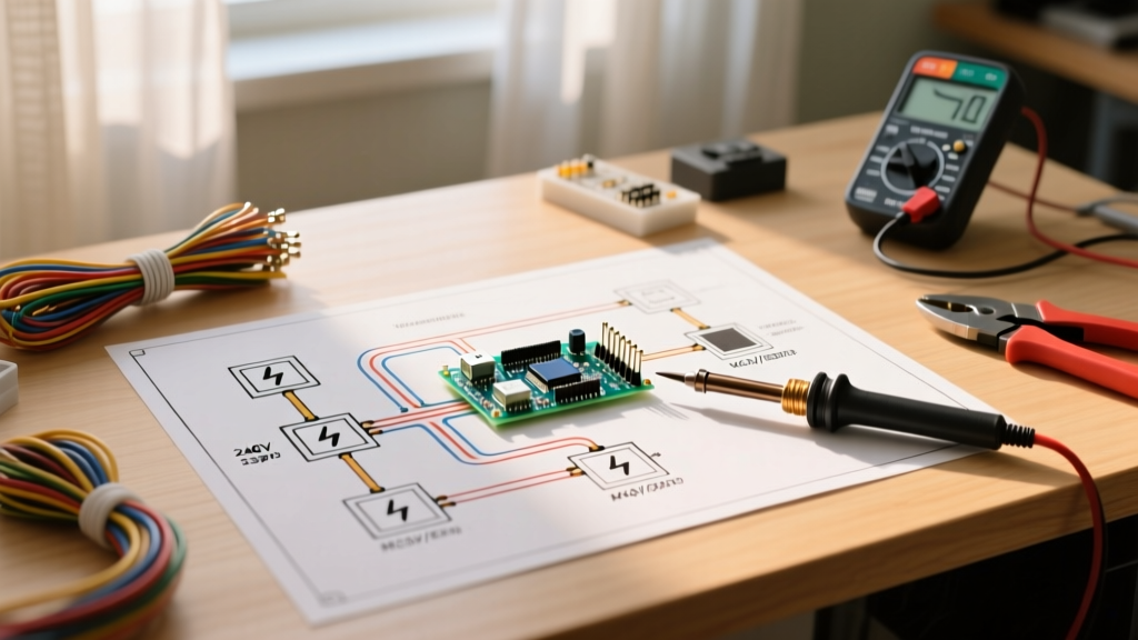
For this walkthrough, we are using a standard electric wiring diagram for a 30-Amp, 240-Volt electric water heater connected to a Square D QO230 double-pole breaker. Follow these steps sequentially.
Step 1: Lockout and Verify
Shut off the main breaker if you are installing a new sub-panel, or shut off the specific branch breaker if tapping into an existing bus. Apply your LOTO padlock. Use your Fluke 117 to test Line-to-Line (L1 to L2), Line-to-Ground (L1 to Ground, L2 to Ground), and Line-to-Neutral. The meter must read 0.00V.
Step 2: Route and Prepare the Cable
Run your 10/2 NM-B (Romex) or 10 AWG THHN in conduit from the panel to the appliance. If using THHN, pull three wires: Black (Hot 1), Red (Hot 2), and Bare Copper (Ground). Pro Tip: Leave at least 18 inches of slack inside the panel. The NEC requires minimum wire bending space; cramming wires violates code and stresses the terminals.
Step 3: Strip and Land the Ground
Strip exactly 3/4 inch of insulation from the hot wires using your Klein strippers. Always land the bare ground wire on the equipment grounding bus bar first. Tighten the ground lug to the manufacturer's specified torque (typically 35-45 in-lbs for 10 AWG copper). This ensures that if a fault occurs while you are working, the path to ground is already established.
Step 4: Terminate the Hot Legs (L1 and L2)
Insert the stripped Black wire into the L1 terminal of the Square D QO230 breaker. Insert the Red wire into L2. Using your calibrated torque screwdriver, tighten the terminal screws to exactly 45 inch-pounds. Under-torquing causes arcing and fires; over-torquing strips the screw threads or crushes the copper strands, increasing resistance.
Step 5: Snap in the Breaker and Dress the Wires
Firmly press the breaker onto the hot bus stab. Route the Black and Red wires neatly along the side of the panel gutter, securing them with nylon cable ties every 12 inches. Keep low-voltage and high-voltage wires separated to prevent inductive interference, though this is less critical in pure 240V resistive loads like water heaters.
Phase 4: Verification, Testing, and Energization
Before removing your LOTO device, perform a final visual inspection against your electric wiring diagram. Check for 'whiskers'—tiny strands of copper that escape the terminal block and could bridge to the neutral bus or grounded enclosure.
Expert Insight: If your diagram calls for a neutral wire (common in appliances with 120V control boards, like modern dryers or ranges), ensure the neutral is landed only on the neutral bus bar, never the ground bus. In a main service panel, they are bonded, but in a sub-panel, mixing them creates a parallel neutral path, violating NEC Article 250 and creating a severe shock hazard.
Remove the lock, stand to the side of the panel (never stand directly in front when energizing), and flip the breaker to the ON position. Use your multimeter to verify 240V at the appliance terminal block (L1 to L2).
Troubleshooting: When the Physical Wire Doesn't Match the Diagram
Even with a perfect electric wiring diagram, field conditions often introduce variables. Here is how to handle common discrepancies:
- Missing Terminal Numbers: Older equipment may have worn-off terminal labels. Use the continuity setting on your multimeter to trace the internal PCB traces back to the relay coils to identify NO/NC contacts manually.
- Color Code Mismatches: If replacing an old 3-wire appliance with a modern 4-wire setup, the diagram will show a separate ground and neutral. You must remove the bonding strap on the appliance's terminal block that ties neutral to the chassis ground, otherwise, you will energize the appliance chassis with return current.
- Voltage Drop on Long Runs: If your diagram specifies 10 AWG but the run exceeds 100 feet, you must upsize to 8 AWG to mitigate voltage drop. The diagram assumes standard run lengths; as the installer, you must calculate the voltage drop (aim for less than 3% on branch circuits).
Final Thoughts on Diagram Literacy
Mastering the electric wiring diagram is about more than just connecting Point A to Point B. It is about understanding the intent behind the design, respecting the physical limitations of the materials, and adhering strictly to safety codes. By taking a methodical, step-by-step approach—verifying symbols, prepping wires to exact measurements, and torquing terminals to specification—you ensure a safe, code-compliant, and long-lasting electrical installation.