
Anatomy of a 240V Baseboard Heater Circuit
Installing a 240-volt baseboard heater is one of the most efficient ways to supplement or establish zone heating in a residential or commercial space. However, unlike standard 120V receptacle circuits, a 240V circuit utilizes two ungrounded (hot) conductors, meaning there is no neutral wire involved in the heating element itself. This fundamental difference dictates a unique wiring diagram, specific wire gauge requirements, and strict adherence to National Electrical Code (NEC) color standards.
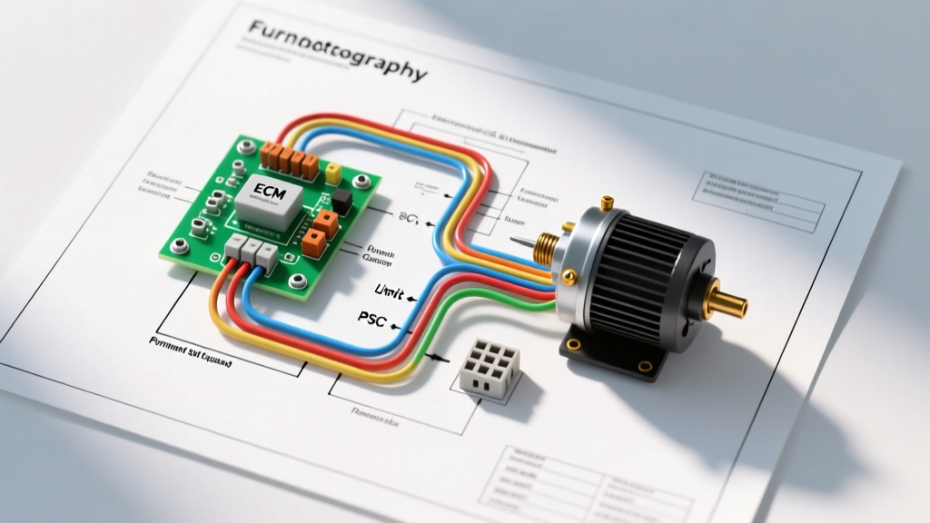
The core wiring diagram for a 240V baseboard heater follows a direct, dedicated path: Main Service Panel → Double-Pole Circuit Breaker → 2-Wire Cable with Ground → Line-Voltage Thermostat → Baseboard Heater Element. Because fixed electric heating is classified as a continuous load under the NEC, the circuit must be engineered to handle 125% of the heater’s maximum rated current, heavily influencing your wire gauge and breaker selection.
Wire Gauge and Breaker Sizing Matrix (The 125% Rule)
According to NFPA 70 (NEC) Article 424.3(B), branch circuits supplying fixed electric heating equipment must be calculated as continuous loads. This means a heater drawing 16 amps continuously requires a circuit rated for at least 20 amps (16 x 1.25 = 20). Undersizing the wire or breaker is a primary cause of thermal degradation and electrical fires.
The following matrix provides the exact wire gauge (AWG) and breaker sizing for standard 240V baseboard heaters using copper NM-B (Romex) or THHN in conduit:
| Heater Wattage (240V) | Actual Amp Draw | Required Circuit Capacity (125%) | Min. Wire Gauge (Copper) | Breaker Size (2-Pole) |
|---|---|---|---|---|
| 500W - 1000W | 2.1A - 4.2A | 5.25A | 14 AWG (12 AWG preferred) | 15 Amp (20A preferred) |
| 1500W | 6.25A | 7.8A | 12 AWG | 15 Amp or 20 Amp |
| 2000W | 8.3A | 10.4A | 12 AWG | 20 Amp |
| 2500W - 3000W | 10.4A - 12.5A | 15.6A | 12 AWG | 20 Amp |
| 3500W - 4000W | 14.6A - 16.6A | 20.8A | 10 AWG | 30 Amp |
| 4500W - 5760W | 18.7A - 24.0A | 30.0A | 10 AWG | 30 Amp |
Note: While 14 AWG is technically permissible for loads under 12A on a 15A breaker, professional electricians almost universally standardize on 12 AWG for 240V heater circuits to provide mechanical strength, reduce voltage drop, and allow for future heater upgrades without rewiring.
NEC Color Code Standards and the "White Wire" Re-identification
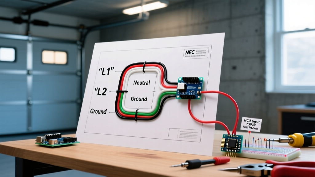
One of the most frequent code violations in DIY baseboard heater installations involves the misuse of the white wire in standard 2-wire NM-B cable (e.g., 12/2 or 10/2 Romex). In a standard 120V circuit, white is strictly reserved for the grounded neutral conductor. However, a 240V baseboard heater does not require a neutral.
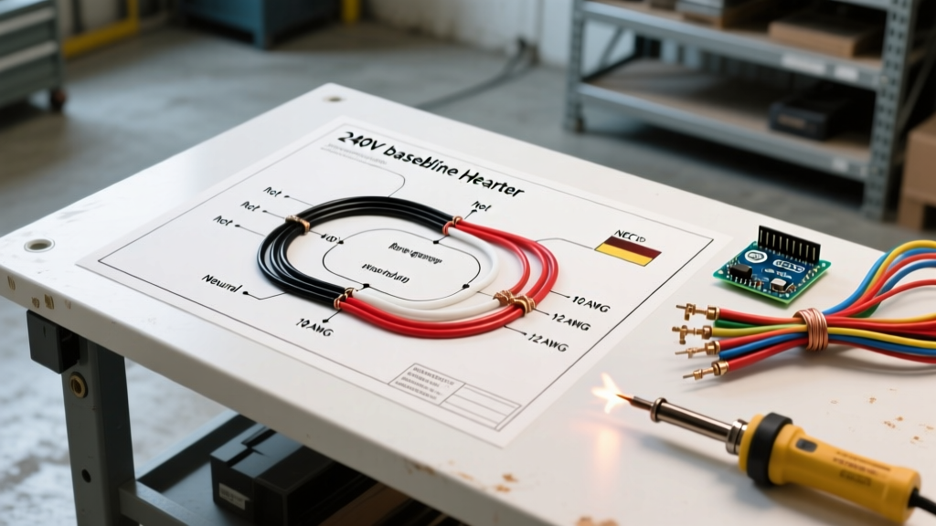
In a 240V diagram, both the black and white wires serve as ungrounded (hot) conductors, each carrying 120V relative to ground, and 240V relative to each other. According to NEC Article 200.7(C)(1) and (C)(2), if you use a white wire as a hot leg, it must be permanently re-identified at every point the wire is accessible (at the panel, in the thermostat junction box, and at the heater junction box).
Proper Color Coding for 240V Heater Circuits:
- Black Wire: Line 1 (Hot 1) - Connects to one pole of the double-pole breaker and one side of the thermostat.
- White Wire (Re-identified): Line 2 (Hot 2) - Must be wrapped with black or red electrical tape (or heat shrink) at the ends. Connects to the second pole of the breaker and the opposite side of the thermostat/heater.
- Bare Copper / Green: Equipment Grounding Conductor - Must be bonded to the panel ground bus, the thermostat junction box (if metal), and the heater chassis ground screw.
Line-Voltage Thermostat Wiring: Single-Pole vs. Double-Pole
The wiring diagram changes slightly depending on whether you are using a single-pole or double-pole line-voltage thermostat (such as the Honeywell TL7235A or Cadet B-Mech).
Single-Pole Thermostat Wiring
A single-pole thermostat only breaks one of the 120V hot legs. While this allows the thermostat to control the heat output, the heating element remains energized with 120V on the other leg even when the thermostat is turned "off."
- Panel to Thermostat: Black and White (re-identified) enter the thermostat box.
- Thermostat to Heater: Black connects to the thermostat's Line 1, then loads out to Heater Lead 1. The White (re-identified) bypasses the thermostat and wires directly to Heater Lead 2 via a wire nut.
Double-Pole Thermostat Wiring (Recommended)
A double-pole thermostat breaks both hot legs simultaneously. When turned off, the heater is completely de-energized, which is a critical safety feature for maintenance and is required by code in several jurisdictions.
- Panel to Thermostat: Black (Line 1) and White/Red (Line 2) connect to the "LINE" terminals on the thermostat.
- Thermostat to Heater: Two separate load wires exit the "LOAD" terminals on the thermostat and connect directly to the two heating element leads in the baseboard junction box.
2026 Installation Costs and Material Pricing
Budgeting for a 240V baseboard heater installation requires accounting for current material costs. As of early 2026, copper prices have stabilized, but smart-home integrations have shifted the thermostat market.
- 12/2 NM-B Cable: ~$0.65 per linear foot.
- 10/2 NM-B Cable: ~$1.15 per linear foot.
- 20A Double-Pole Standard Breaker: $12 - $18 (Square D Homeline or Siemens).
- 20A Double-Pole AFCI/GFCI Breaker: $45 - $65 (Required in some 2026 NEC jurisdictions for living areas).
- Standard Mechanical Line-Voltage Thermostat: $35 - $50.
- Smart Line-Voltage Thermostat (e.g., Mysa): $110 - $140 (Note: Many smart thermostats require specific 2-wire or 4-wire configurations; always verify the diagram against your specific model).
Common Failure Modes and Edge Cases
Even with the correct wiring diagram, improper execution leads to hazardous failure modes. Understanding these edge cases separates professional installations from amateur hazards.
Voltage Drop on Long Runs
If the circuit run from the main panel to the baseboard heater exceeds 50 feet, voltage drop becomes a critical factor. A 240V circuit experiencing a 5% voltage drop will only deliver 228V to the heater. Because heating elements are resistive, lower voltage results in a squared drop in wattage output (P = V²/R). A 2000W heater will only produce roughly 1800W of heat. For runs over 75 feet, always upsize the wire gauge (e.g., use 10 AWG on a 20A circuit) to maintain efficiency and prevent the wire from operating near its thermal limit.
Terminal Torque and Thermal Creep
Baseboard heaters generate significant ambient heat, which can cause "thermal creep" in wire connections—a phenomenon where repeated heating and cooling cycles cause terminal screws to loosen over time. Loose connections increase electrical resistance, leading to localized arcing, melted wire insulation, and potential fires. Always use a calibrated torque screwdriver (such as the Klein Tools 32308) to tighten terminal lugs to the manufacturer's specification, typically 12 to 14 in-lbs for 12 AWG and 10 AWG conductors.
Conduit Fill and Derating
If you are pulling THHN/THWN wires through EMT conduit rather than using NM-B cable, be aware of NEC Chapter 9, Table 1 regarding conduit fill. If you run more than three current-carrying conductors in a single conduit (for example, wiring two separate 240V heaters in the same pipe), you must apply the derating factors in NEC Table 310.15(C)(1). Four to six conductors require an 80% derating factor, meaning a 12 AWG wire (normally rated for 25A in THHN) is derated to 20A, which perfectly aligns with a 20A breaker, but leaves zero margin for error.
Authoritative References and Safety Standards
Proper electrical installation is not just about following a diagram; it is about complying with life-safety codes. For further reading on fixed electric heating equipment and general electrical safety, consult the following authoritative resources:
- National Fire Protection Association (NFPA) - NFPA 70: National Electrical Code (NEC): The definitive standard for all wiring methods, specifically Article 424 for Fixed Electric Heating Equipment.
- U.S. Department of Energy - Baseboard Heaters: Comprehensive guidelines on the energy efficiency, placement, and operational safety of electric baseboard heating systems.
- OSHA - 1910.303 General Requirements for Electrical Safety: Federal regulations regarding the examination, installation, and use of electrical equipment in commercial and workplace environments.
Disclaimer: Electrical work carries inherent risks of shock, arc flash, and fire. Always turn off the main breaker and verify the absence of voltage with a CAT III or CAT IV multimeter before beginning work. If you are unsure about local code requirements regarding AFCI protection or wire routing, consult a licensed master electrician.