
Strategic Planning for Occupancy and Vacancy Sensor Upgrades
Upgrading a standard toggle switch to an automated sensor is one of the highest-ROI electrical projects a homeowner or facility manager can undertake. According to the U.S. Department of Energy's guide on lighting controls, automated occupancy sensors can reduce lighting energy consumption by 30% to 50% in commercial spaces and up to 20% in residential zones like garages and hallways. However, the physical installation is only as successful as the planning phase. Misinterpreting a wiring diagram for motion sensor switch configurations is the leading cause of tripped breakers, fried internal relays, and 'ghosting' LEDs. This installation planning guide provides the deep technical specifics required to map your circuit, verify box capacity, and select the correct sensor topology before you ever strip a wire.
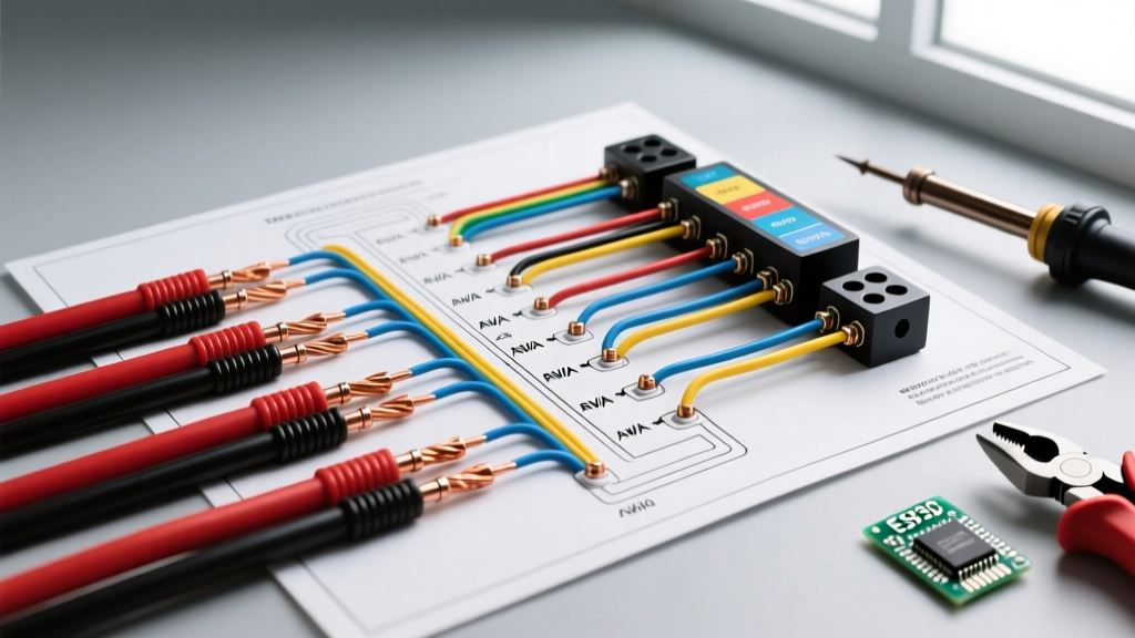
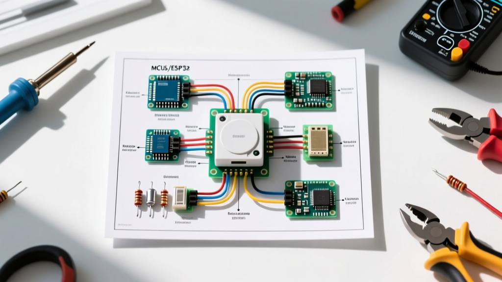
Decoding the Standard Wiring Diagram for Motion Sensor Switch Installs
Unlike a basic single-pole mechanical switch that only interrupts the hot (line) wire, modern motion sensors are active electronic devices. They require a complete circuit to power their internal PIR (Passive Infrared) or ultrasonic microprocessors. When reviewing your wiring diagram, you must identify four critical conductors in your gang box:
- Line (Hot): Typically black (or red in some 3-way setups). This brings 120V/240V constant power from the breaker panel. It connects to the sensor's 'Line' or 'Hot' terminal.
- Load: Typically black or red with yellow tape. This carries the switched power down to the light fixture. It connects to the sensor's 'Load' terminal.
- Neutral: White or gray. This completes the 120V circuit to power the sensor's internal logic board. It connects to the sensor's 'Neutral' terminal and must be pigtailed to the existing bundle of white wires in the back of the box.
- Ground: Bare copper or green. Essential for safety and EMI (Electromagnetic Interference) shielding. Connects to the green ground screw on the sensor yoke and the box grounding pigtail.
The Neutral Wire Dilemma in Pre-2020 Construction
If you are working in a home built before the 2011 NEC (National Electrical Code) cycle, your switch boxes likely lack a neutral wire. Older codes only required the hot and switched-hot (load) wires to be pulled to the switch location. While 'no-neutral' motion sensors exist (such as the Lutron Maestro MS-OPS2H), they operate by leaking a tiny trickle of current through the lighting load to keep their internal capacitors charged. In 2026, with the dominance of low-wattage LED fixtures, this trickle current often causes 'ghosting'—where LEDs remain dimly lit or flicker when the sensor is off. For any new installation planning, verifying the presence of a neutral wire is non-negotiable for optimal performance.
Sensor Technology and Load Compatibility Matrix
Choosing the right sensor goes beyond matching the wiring diagram; it requires matching the sensor's detection technology to the room's geometry and the electrical load's characteristics. Below is a decision matrix for 2026 sensor planning:
| Sensor Technology | Detection Method | Best Application | Avg. Cost (2026) | Wiring Complexity |
|---|---|---|---|---|
| PIR (Passive Infrared) | Detects body heat movement across a grid | Hallways, garages, closets (clear line of sight) | $25 - $40 | Standard (Line, Load, Neutral, Ground) |
| Ultrasonic | Bounces high-frequency soundwaves off surfaces | Restrooms, offices with partitions (can 'see' around corners) | $45 - $65 | Standard (Line, Load, Neutral, Ground) |
| Dual-Tech (PIR + Ultrasonic) | Requires both heat and motion to trigger (AND logic) | Large warehouses, classrooms (prevents false triggers from HVAC) | $70 - $110 | Standard, sometimes requires 24V low-voltage relay |
| Smart/Matter-Enabled | PIR + Ambient Light + Network Radio | Integrated smart homes, automated daylight harvesting | $85 - $140 | Requires Neutral; may need hub or Thread border router |
LED Inrush Current: The Silent Relay Killer
A critical failure mode in motion sensor planning is ignoring LED inrush current. While an LED fixture may draw only 40 watts continuously, its internal driver capacitors can draw an inrush current of up to 100 Amps for a few microseconds upon startup. If your wiring diagram connects a sensor rated for 150W of incandescent load to a 150W equivalent LED load, the inrush will quickly weld the sensor's internal mechanical relay shut, causing the lights to stay on permanently. Always select sensors with heavy-duty triacs or zero-cross switching relays specifically rated for LED/CFL loads, such as the Leviton DOS05 or Eaton OSM10M.
Planning for 3-Way and Multi-Location Circuits
Wiring a motion sensor in a 3-way circuit (where two switches control one light, like at the top and bottom of a staircase) drastically alters the wiring diagram. You cannot simply install two motion sensors in a standard 3-way configuration. The internal logic boards will conflict, causing erratic timing and voltage drops.
The Correct 3-Way Planning Strategy:
- Master/Companion Setup: Install the motion sensor at the primary entry point (Master) and a specialized companion switch at the secondary location (e.g., Lutron MA-R). The wiring diagram for this setup uses the traveler wires to carry digital signaling or switched hot, rather than traditional 3-way toggling.
- Dual-Sensor Setup (Advanced): If both locations require motion detection, you must wire the sensors in parallel. Both sensor 'Line' terminals connect to the constant hot, and both 'Load' terminals are wire-nutted together to feed the fixture. However, you must configure one sensor as the 'Master' (controlling the relay) and the other as a 'Remote' (sending a trigger signal), which requires specific commercial-grade sensors with remote input terminals.
Physical Box Fill and Placement Calculations
The National Fire Protection Association (NFPA) NEC guidelines strictly govern box fill calculations under Article 314.16. Motion sensors have bulky internal electronics that protrude up to 1.5 inches into the gang box. A standard 14-cubic-inch single-gang box will physically reject the sensor body once the 12 AWG or 14 AWG wires and wire nuts are added.
- Box Volume Requirement: Plan to upgrade to a deep 22.5 cubic-inch single-gang box (e.g., Carlon B122R) or a 2-gang box with a 1-gang mud ring.
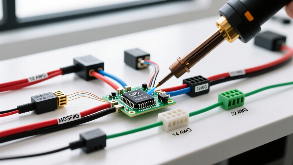
- Wire Gauge Mapping: Ensure your sensor's lead wires match the circuit. Most sensor pigtails are 14 AWG (stranded). If connecting to a 20-Amp circuit with 12 AWG solid wire, use appropriately rated purple or yellow wire nuts to prevent loose connections and arcing.
- Placement Constraints: PIR sensors require a clear line of sight. Do not plan a sensor location behind an open door, directly above an HVAC supply vent (rapid temperature changes cause false triggers), or facing a window with direct sunlight.
Step-by-Step Pre-Installation Checklist
Before cutting power and removing the old switch, complete this planning checklist to ensure a seamless installation:
- Verify Circuit Amperage: Check the breaker (15A or 20A) and confirm the sensor's maximum amperage rating exceeds the circuit limit.
- Test for Neutral: Use a non-contact voltage tester and a multimeter to confirm the presence of a neutral bundle in the back of the box.
- Calculate Total LED Wattage: Add up the actual wattage (not equivalent wattage) of all fixtures on the circuit. Ensure it is at least 20% below the sensor's maximum LED rating.
- Map the Travelers (If 3-Way): Label existing traveler wires with tape before disconnecting the old 3-way switch to match the new companion switch diagram.
- Check for Dimmer Compatibility: If the circuit includes a dimmer, the wiring diagram must place the dimmer on the load side, or you must purchase a sensor with integrated dimming capabilities. Standard sensors will fail if placed downstream of a phase-cut dimmer.
Troubleshooting Common Edge Cases
Even with a perfect wiring diagram execution, environmental factors can cause issues. If the sensor experiences 'dropout' (lights turning off while the room is occupied), the PIR lens may be obstructed, or the sensitivity potentiometer inside the sensor housing needs adjustment. If the lights turn on randomly with no occupants, check for 'thermal cross-talk.' This occurs when a sensor is mounted on a wall shared with a bathroom or kitchen, and heat transfer through the drywall triggers the infrared grid. In these edge cases, applying a piece of electrical tape over the specific offending zone on the sensor's Fresnel lens will block the thermal anomaly without replacing the unit.
Pro Tip for 2026 Smart Integrations: If you are wiring a Matter-over-Thread motion sensor, ensure your gang box has adequate depth not just for the wires, but for the integrated antenna. Crowding copper ground wires directly against the sensor's PCB antenna can cause signal attenuation, leading to dropped connections in your smart home hub.