
Pre-Installation: NEC Code & Fan-Rated Box Requirements
Before pulling a single wire or stripping insulation, successful fan installation hinges on structural and code compliance. The most critical error in DIY and junior-pro installations is mounting a ceiling fan to a standard light fixture junction box. According to NFPA 70 (NEC) Article 314.27(D), any ceiling-mounted outlet box that supports a ceiling fan must be listed and marked as suitable for that purpose.
Standard plastic or lightweight metal boxes are rated for static loads up to 50 lbs. However, a ceiling fan introduces dynamic rotational torque and vibration. For installation planning, you must procure a fan-rated box. If you are retrofitting an existing non-rated box, the Raco 936 Old Work Fan Brace (retailing around $14-$18) is the industry standard. It expands between the ceiling joists and provides a steel-rated box capable of supporting up to 70 lbs.
Safety Warning: Never rely on drywall anchors or standard plastic remodel boxes for fan support. The dynamic vibration will eventually cause metal fatigue or drywall crumbling, leading to catastrophic fixture detachment.
Essential Tool & Material Checklist
- Voltage Tester: Klein Tools NCVT-3 (Non-contact) and a digital multimeter for verifying zero-energy state.
- Wire Connectors: Ideal WireNuts 341 (Blue) for joining 14 AWG or 12 AWG solid-to-stranded fan leads.
- Cable Staples/Supports: If running new NM-B (Romex) cable, secure within 8 inches of the box per NEC 334.30.
- Stripping Tools: Klein 11063W wire strippers to avoid nicking the copper conductor, which creates a hot spot under load.
Deconstructing the Standard Electrical Fan Wiring Diagram
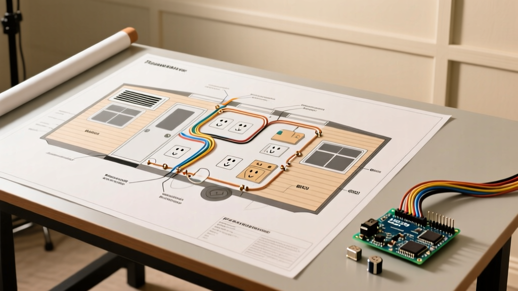
When reviewing a standard electrical fan wiring diagram for a residential ceiling fan with an integrated light kit, you are typically dealing with a dual-function circuit. This requires a 3-wire plus ground cable (e.g., 14/3 or 12/3 NM-B) running from the dual-gang wall switch to the ceiling canopy.
The 3-Wire Plus Ground Configuration
In this planning scenario, the wall switch location receives line voltage (120V AC). The power is split to two separate single-pole switches (or a stacked duplex switch like the Leviton 16262). The 3-wire cable carries the switched legs up to the fan canopy:
- Black Wire (Switched Leg 1): Connects to the fan motor's black lead (Fan Power).
- Red Wire (Switched Leg 2): Connects to the light kit's blue lead (Light Power).
- White Wire (Neutral): Connects to both the fan motor's white lead and the light kit's white lead. This completes the 120V circuit.
- Bare/Green Wire (Ground): Must be bonded to the green ground screw on the fan mounting bracket, the metal junction box, and the fan motor's green pigtail.
If your installation only has a 2-wire cable (14/2 or 12/2) available at the ceiling, the black and blue leads on the fan must be pigtailed together and connected to the single black switched leg. In this scenario, independent wall control of the light and fan is impossible without installing a smart canopy receiver module.
Wire Gauge, Circuit Sizing, and Load Matrix
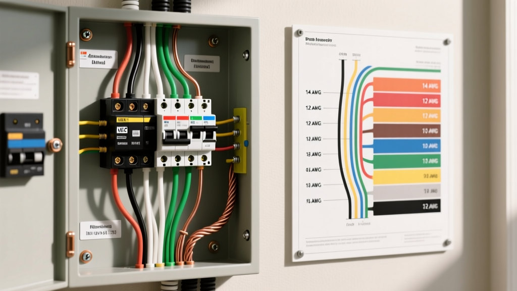
Selecting the correct wire gauge is dictated by the breaker size and the total continuous load on the circuit. While most residential lighting circuits are 15-amp (14 AWG), modern ENERGY STAR certified fans utilize highly efficient DC motors that draw significantly less current than legacy AC induction motors.
| Fan Type / Application | Motor Type | Avg. Amp Draw | Min. Wire Gauge | Breaker Size |
|---|---|---|---|---|
| Standard 52" Residential (AC Motor) | AC Induction | 0.6A - 1.2A | 14 AWG | 15 Amp |
| High-Efficiency 60" (DC Motor) | Brushless DC | 0.2A - 0.5A | 14 AWG | 15 Amp |
| Large Commercial / Industrial (72"+) | Heavy Duty AC | 2.5A - 4.0A | 12 AWG | 20 Amp |
| Inline Exhaust Fan (Bathroom) | Shaded Pole | 0.8A - 1.5A | 14 AWG | 15/20 Amp (AFCI/GFCI) |
Note: If the fan circuit shares a breaker with high-draw appliances or bathroom receptacles (which require 20-amp circuits per NEC 210.11(C)(3)), you must upgrade to 12 AWG THHN or 12/2 NM-B wire to prevent thermal overload.
Advanced Configurations: Capacitors and Multi-Speed Motors
For installations involving legacy AC fans or specific commercial exhaust setups, understanding the internal electrical fan wiring diagram regarding speed control is vital. Most 3-speed AC ceiling fans utilize a CBB61 polypropylene film capacitor located inside the switch housing.
The CBB61 capacitor typically has 3 to 5 wires and contains multiple microfarad (µF) ratings (e.g., 4.5µF + 6µF + 8µF). The pull-chain switch cycles through different taps on the capacitor to alter the phase angle of the auxiliary motor winding, thereby controlling speed. If you are replacing a faulty switch or capacitor during a retrofit:
- Failure Mode: Fan only runs on high speed or hums on low/medium.
- Diagnosis: The internal dielectric of one of the capacitor chambers has degraded. Capacitors do not repair; they must be replaced with an exact µF and voltage match (usually 250V AC or 450V AC).
- Wiring Sequence: The line-in (from the wall) goes to the switch 'L' terminal. The switch outputs (1, 2, 3) route to the specific capacitor taps, which then feed the motor's auxiliary winding.
Smart Switch Integration: Bypassing the Pull-Chain
In 2026, hardwired smart home ecosystems are the standard for premium installations. If your installation plan involves smart controls, you must account for neutral wire requirements and inductive load spikes.
For Wi-Fi or Zigbee fan control, the Lutron Caseta PD-FSQ5X (approx. $75) is specifically designed for ceiling fan motor control. Standard smart dimmers (like the Lutron PD-6WCL) must never be used on a fan motor. Dimmers chop the AC sine wave using TRIACs, which causes severe harmonic distortion in an inductive motor load. This results in a loud 60Hz electrical hum, excessive heat generation, and eventual motor winding failure.
Planning Requirement: Smart fan switches require a neutral wire at the wall box to power the internal radio transceiver. If your older home's switch loop only contains a 2-wire cable (Line and Load, no Neutral), you must either pull a new 14/3 cable to the switch box or utilize a canopy-mounted smart receiver (like the Bond Bridge or Hunter SIMPLEconnect module) that draws its standby power from the always-hot line and neutral at the ceiling.
Real-World Failure Modes & Edge Cases
Even with a perfect electrical fan wiring diagram, field conditions introduce variables that can derail an installation. Anticipate these edge cases during your planning phase:
1. AFCI Nuisance Tripping
Modern electrical panels utilize Arc Fault Circuit Interrupters (AFCIs) for bedroom and living room circuits. Large AC fan motors generate a brief inductive voltage spike (back-EMF) when switched off. In older AFCI breakers, this spike mimics an arc fault signature, causing the breaker to trip. Solution: Ensure the panel is equipped with 2023/2026 generation AFCI breakers with advanced algorithmic filtering, or install a dedicated RC snubber circuit across the fan motor leads to absorb the transient voltage.
2. Reverse Rotation & Phase Issues
If a newly wired exhaust or ceiling fan is pulling air upward instead of pushing it downward (in the forward switch position), the start and run windings may be out of phase. On single-phase AC motors, reversing the polarity of the auxiliary winding relative to the main winding reverses the motor direction. Check the manufacturer's schematic; swapping the black and red leads on the capacitor block will usually reverse the rotation.
3. Canopy Vibration and Harmonic Rattle
Electrical wiring that is loosely bundled inside the canopy can vibrate against the metal housing, creating a persistent rattling noise that mimics a failing motor bearing. Pro-Tip: Use foam tape or carefully route the 14 AWG wires into the deepest recess of the junction box, securing them with a single piece of electrical tape to prevent acoustic transfer to the canopy cover.
Final Inspection & Commissioning
Once the physical wiring is terminated, do not immediately attach the fan blades. Power the circuit and test the motor rotation, light kit function, and smart switch pairing. Consult the Hunter Fan Installation Support archives for model-specific dip-switch configurations if you are pairing a remote receiver. Only after verifying electrical continuity, correct rotation, and stable smart-network integration should you mount the blades and finalize the canopy. Proper planning using these diagram principles ensures a safe, code-compliant, and silent operation for decades.