
Understanding Manufactured Home HVAC Electrical Systems
Wiring an electric furnace in a manufactured home requires strict adherence to specialized electrical codes that differ from standard site-built residential construction. When analyzing a mobile home electric furnace wiring diagram, technicians and DIYers must account for the unique constraints of the HUD Code (24 CFR Part 3280) and NEC Article 550. In 2026, the vast majority of mobile homes rely on downflow electric furnaces, with the Nordyne (Miller) E7EB series and Intertherm E5/E7 lines dominating the market.
Unlike gas furnaces that require 120V for the blower and gas valve, mobile home electric furnaces demand high-amperage 240V circuits to power resistive heating elements, alongside a stepped-down 24V control circuit for the thermostat and relays. Misinterpreting the wiring schematic can lead to catastrophic inrush current trips, melted terminal blocks, or severe fire hazards.
CRITICAL SAFETY WARNING: Mobile home electrical panels are often limited to 100A or 150A total capacity. A 15kW electric furnace alone draws 62.5 Amps. Never upgrade furnace heating elements without verifying the main breaker capacity and calculating the continuous load per NEC Article 220. Always disconnect the main power at the exterior disconnect before opening the furnace blower compartment.Core Components in the Wiring Schematic
To accurately read the wiring diagram, you must identify the primary control and safety components unique to manufactured home electric furnaces. Standard site-built homes often use heavy-duty contactors for electric heat; mobile homes use a different approach to manage power grid strain.
The Sequencer vs. The Contactor
The most critical distinction in a mobile home electric furnace wiring diagram is the use of sequencers instead of standard contactors. A standard contactor closes all high-voltage contacts simultaneously. If a 15kW furnace (three 5kW elements) energized all at once, the massive inrush current would cause severe voltage drop, dimming lights and potentially tripping the main panel breaker.
Sequencers (such as the ubiquitous White-Rodgers 586-902 or Honeywell L4064) use a 24V bimetallic heater coil. When the thermostat calls for heat, the 24V coil warms up, closing the high-voltage contacts in staggered intervals:
- Stage 1 (First Element & Blower): Closes in 12 to 18 seconds.
- Stage 2 (Second Element): Closes in 20 to 30 seconds.
- Stage 3 (Third Element): Closes in 30 to 45 seconds.
This staggered loading protects the mobile home's main electrical service and prevents voltage sags.
Auto-Reset Limit Switches
Downflow furnaces push heated air downward through the floor registers. If the blower fails or airflow is restricted, heat builds up rapidly in the element box. The wiring diagram routes the 24V control circuit through an auto-reset bimetallic limit switch (typically rated to open at 130°F and close at 90°F). If this switch opens, it breaks the 24V path to the sequencer coil, shutting off the heat while allowing the blower to continue running to clear residual heat.
Step-by-Step Wiring Walkthrough: Nordyne E7EB Series
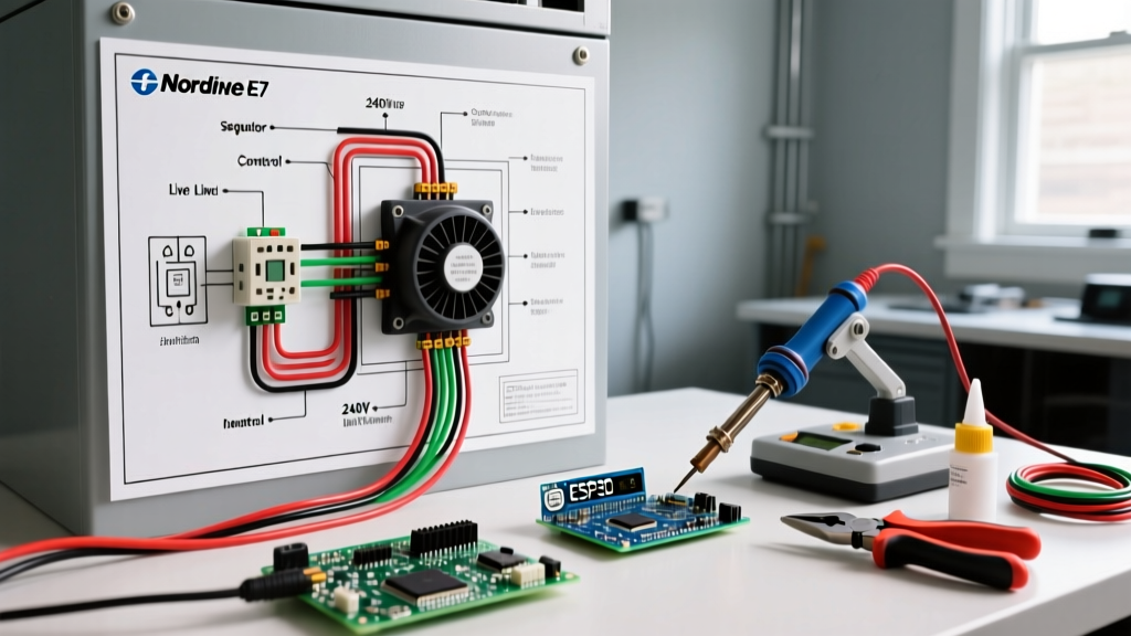
The Nordyne E7EB downflow furnace is the industry standard for replacement units in 2026. Below is the logical flow of the wiring diagram from the main panel to the heating elements.
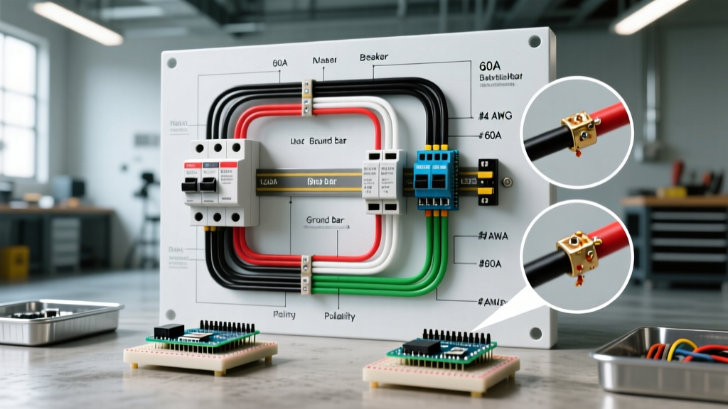
- Main Power Entry: 240V enters the furnace via a 2-pole breaker. The black and red (Line 1 and Line 2) wires connect to the main terminal block. The white wire (neutral) and bare/green wire (ground) connect to their respective isolated buses.
- Transformer Primary: 240V is tapped from the terminal block to the primary side of a 40VA step-down transformer.
- Control Circuit (24V): The secondary side of the transformer outputs 24V AC. One leg goes to the 'R' terminal on the thermostat terminal strip. The other leg routes through the limit switch, then to the 'W' terminal.
- Sequencer Coil: When the thermostat closes the 'W' circuit, 24V travels to the C1/C2 terminals on the sequencer coil, initiating the heating delay.
- Element Energization: Line 1 passes directly through the heating elements. Line 2 passes through the sequencer's high-voltage contacts (H1/H2, H3/H4). When the contacts close, the 240V circuit is completed, and the elements glow.
Wire Gauge & Circuit Breaker Sizing Matrix
Selecting the correct wire gauge is non-negotiable. According to HUD manufactured housing electrical standards, branch circuits must be sized at 125% of the continuous heating load. Use the table below to verify your mobile home's furnace wiring against the manufacturer's data plate.
| Furnace Capacity (kW) | Max Amp Draw (240V) | Required Copper Wire Gauge | Min. 2-Pole Breaker Size |
|---|---|---|---|
| 10 kW | 41.6 Amps | 8 AWG | 50 Amp |
| 15 kW | 62.5 Amps | 6 AWG | 70 Amp |
| 20 kW | 83.3 Amps | 4 AWG | 90 Amp |
Note: Aluminum wire requires sizing up by one gauge (e.g., use 4 AWG Aluminum for a 15kW / 70A circuit). Always check local amendments to the NEC.
Common Wiring Failure Modes & Multimeter Diagnostics
When a mobile home loses heat, the wiring diagram serves as your diagnostic map. Here are the most common failure modes and how to test them using a digital multimeter (DMM).
Scenario A: Blower Motor Runs, But No Heat
This indicates the 24V control circuit is calling for heat and the blower relay is engaged, but the high-voltage sequencer is failing to pass 240V to the elements.
- Step 1: Set DMM to AC Volts. Measure across the sequencer coil terminals (C1 and C2). You should read 24V AC. If you read 0V, the limit switch is open or the thermostat 'W' wire is broken.
- Step 2: If 24V is present at the coil, wait 30 seconds. Set DMM to Continuity/Ohms (with power OFF). Measure across the high-voltage terminals (H1 and H2). If the meter reads 'OL' (infinite resistance), the internal bimetallic switch has failed. Replace the sequencer (approx. $35-$50 for an OEM replacement).
Scenario B: Tripped 240V Breaker Immediately Upon Heat Call
A breaker that trips instantly (not after 30 minutes of running) indicates a dead short. In mobile home furnaces, this is almost always a grounded heating element.
- Diagnostic: Disconnect power. Remove the wires from the heating elements. Set DMM to Ohms. Measure from each element terminal to the furnace chassis ground. A reading of anything less than infinite resistance means the element coil has warped and is touching the metal casing. A replacement 5kW mobile home element costs between $45 and $85 in 2026.
Thermostat Wiring: 18 AWG Color Code Standards
The low-voltage side of the diagram relies on 18 AWG solid copper thermostat wire. While color codes are not strictly mandated by the NEC, the HVAC industry standard for mobile home electric furnaces is:
- Red (R): 24V AC Hot (from transformer secondary).
- White (W): Heat Call (routes through limit switch to sequencer coil).
- Green (G): Blower Fan Call (energizes the blower relay).
- Yellow (Y): Cooling Call (only if a central AC coil is installed in the downflow plenum).
- Blue/Black (C): 24V Common.
2026 Smart Thermostat Upgrade Note: Many mobile homes built before 2010 were wired with 18/3 or 18/4 cable, lacking a 'C' (Common) wire. Modern smart thermostats like the Ecobee SmartThermostat or Nest Learning Thermostat require continuous 24V power. If your diagram lacks a C-wire connection at the wall, you must either pull new 18/5 cable through the floor cavity or install a 24V Add-A-Wire diode kit at the furnace control board.
Frequently Asked Questions (FAQ)
Can I replace a mobile home downflow furnace with a standard upflow unit?
No. Mobile homes are engineered with specific under-floor return air and ducting systems. Furthermore, U.S. Department of Energy guidelines and HUD codes require manufactured home furnaces to be specifically listed for mobile home use (usually indicated by a yellow certification tag). Standard upflow furnaces lack the specialized sealed combustion or specific downflow blower housings required for safe operation in a manufactured home.
Why does my furnace blower run for 90 seconds before the heat turns on?
This is the intended function of the sequencer. The 24V coil takes time to heat the bimetallic strip. This delay ensures the blower is moving air across the elements before they reach glowing temperatures, preventing the limit switch from tripping due to localized heat buildup.
My wiring diagram shows a 'fan center' relay. What is this?
Older Intertherm and Nordyne models used a separate 24V fan center relay to isolate the blower motor's high-voltage contactor from the thermostat. In modern 2026 replacements, this is often integrated directly into the main control board or replaced by a dedicated blower time-delay relay that keeps the fan running for 60-90 seconds after the thermostat satisfies the heat call, extracting residual heat from the element box.