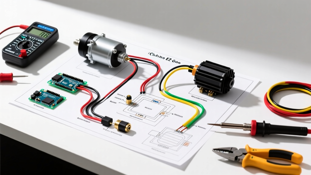

Understanding the 48V Golf Cart Powertrain Architecture
Deciphering a wiring diagram for a golf cart requires more than just matching colors; it demands a fundamental understanding of high-current DC powertrains. Whether you are upgrading a vintage 1998 EZ-GO TXT to a modern lithium-ion setup or replacing a burnt-out controller on a 2015 Club Car Precedent, the motor wiring topology remains the critical bottleneck for performance and safety. In 2026, the shift from traditional DC Series motors to AC induction and SepEx (Separately Excited) DC motors has changed how technicians approach terminal mapping, regenerative braking circuits, and encoder integrations.
This motor wiring tutorial dissects the exact routing, wire gauge requirements, and terminal assignments for standard 48V electric golf carts. We will bypass generic advice and focus on actionable, bench-tested specifications used by professional EV conversion shops.
Core Components and Sourcing Costs (2026 Market)
Before cutting a single length of battery cable, verify your component compatibility. Mismatching a SepEx motor with a Series controller will instantly destroy the controller's internal MOSFETs upon key-on. Below is a breakdown of standard 48V powertrain components and their current market pricing.
| Component | Common Model / Spec | Function in Circuit | 2026 Avg. Cost |
|---|---|---|---|
| Motor Controller | Curtis 1268-5403 (SepEx) | Modulates DC battery power into phased motor current | $480 - $620 |
| Heavy-Duty Solenoid | Albright SW200 (48V) | Acts as the main high-current relay (contactor) | $45 - $65 |
| Throttle Input | Club Car MCOR3 (4-Pin) | Translates pedal travel to a 0-5kΩ or 0-5V logic signal | $110 - $140 |
| Main Power Cable | 2 AWG Welding Cable | Carries 200A+ peak current from batteries to controller | $2.80 / ft |
| Precharge Resistor | 470Ω, 2W Carbon Film | Pre-charges controller capacitors to prevent solenoid arcing | $0.15 |
Step-by-Step Motor Wiring Tutorial
Step 1: High-Current Battery and Solenoid Routing
The foundation of any golf cart wiring diagram starts at the battery bank. For a 48V system (typically four 12V or six 8V deep-cycle/lithium batteries), the main positive and negative cables must be routed through the main solenoid and controller.
- Main Positive to Solenoid: Run a 2 AWG cable from the main positive battery terminal to the large left terminal of the solenoid. (Use 4 AWG only if your peak draw is strictly under 150A; 2 AWG is the 2026 industry standard for 400A+ peak controllers like the Alltrax SR-48400).
- Solenoid to Controller B+: Run a 2 AWG cable from the large right terminal of the solenoid to the B+ (Battery Positive) terminal on the motor controller.
- The Precharge Circuit (Critical): Never wire a high-amperage solenoid without a precharge resistor. Solder a 470Ω, 2W resistor across the two small terminals of the solenoid. When the key turns on, this resistor allows a tiny trickle of current to charge the controller's massive internal capacitors before the solenoid physically clicks closed. Without this, the inrush current will weld the solenoid contacts together or blow the controller's main fuse.
Pro-Tip from the Bench: If your solenoid clicks rapidly (machine-gunning) when you press the throttle, your precharge resistor is blown, or your controller's internal capacitors are failing. Always test the 470Ω resistor with a multimeter during annual maintenance.
Step 2: Controller-to-Motor Terminal Mapping
This is where most DIY wiring diagrams fail due to a lack of motor-type specificity. You must identify whether your motor is DC Series, DC SepEx, or AC Induction before connecting the heavy phase cables.
- DC Series Motor (e.g., ADC 8" Motor): Features four large terminals: A1, A2, D1, and D2. The controller connects to A1 and A2 (Armature) to dictate speed, while the field (D1/D2) is wired in a continuous loop through the controller to manage torque/forward-reverse magnetic polarity.
- DC SepEx Motor (e.g., Club Car IQ): Also features four terminals, but labeled A1, A2 (Armature) and F1, F2 (Field). The controller independently modulates the field and armature currents. This independent control is what allows SepEx motors to utilize regenerative braking (rolling back down a hill charges the batteries).
- AC Induction Motor (e.g., Yamaha G29 / AC HPEC): Features three heavy phase terminals labeled U, V, and W, plus a delicate multi-pin encoder plug. The controller converts DC battery power into a 3-phase AC sine wave. Swapping any two of the U, V, or W cables will simply reverse the motor's direction without causing damage, unlike DC motors.
DC Series vs. SepEx vs. AC Motor Wiring Matrix
Use this comparison matrix to verify your controller-to-motor wiring topology before applying main power.
| Motor Type | Heavy Terminals | Logic / Sensor Cables | Regen Braking? | Controller Match Requirement |
|---|---|---|---|---|
| DC Series | A1, A2, D1, D2 | None | No (Coasts freely) | Series Controller (e.g., Alltrax SR) |
| DC SepEx | A1, A2, F1, F2 | Temp Sensor (Optional) | Yes (Plug braking) | SepEx Controller (e.g., Curtis 1268) |
| AC Induction | U, V, W | Encoder (Speed/Position) | Yes (Highly efficient) | AC Inverter Controller (e.g., Sevcon) |
Throttle Input and Logic Circuit Integration
The high-current motor wiring is useless without the low-current logic circuit telling the controller when to engage. Modern golf carts use an MCOR (Motor Controller Output Regulator) or a traditional 3-wire potentiometer.
For a standard Club Car Precedent MCOR3 setup, the wiring diagram dictates a 4-pin Molex connector:
- Pin 1 (Red): 5V Reference from Controller
- Pin 2 (White): Signal Return (0V to 5V sweep based on pedal travel)
- Pin 3 (Black): Ground
- Pin 4 (Green): Redundancy / Fault Detection
Edge Case Troubleshooting: If the cart exhibits a "runaway" condition (accelerating without pedal input), the MCOR return spring has failed, or the signal wire is shorting to the 5V reference. Always wire the Tow/Run switch correctly into the controller's logic lockout circuit. In 2026, most lithium BMS (Battery Management Systems) also require a CAN-bus or simple 12V logic tap integrated into this throttle circuit to prevent over-discharge.
Critical Failure Modes and Troubleshooting
When your wiring diagram execution results in a dead cart, use this diagnostic sequence before replacing expensive parts:
- Solenoid Clicks, But No Movement: Check the motor brushes (on DC motors) or verify the U/V/W phase continuity. If the controller's B+ reads 48V but the motor terminals read 0V under load, the controller's internal MOSFET bridge has shorted.
- Controller Melting / Overheating: Almost always caused by undersized battery cables or loose terminal crimps. A loose 2 AWG lug creates high resistance, generating massive heat at the B+ terminal. Always use a calibrated torque wrench (typically 12-15 ft-lbs for 5/16" studs) and apply dielectric grease to prevent corrosion.
- Reverse Polarity Damage: If you accidentally swapped B+ and B- during battery reconnection, the controller's main reverse-polarity diode will explode to save the logic board. Look for a cracked epoxy diode near the main power lugs.
Safety Standards and Wire Ampacity
Adhering to electrical codes is not just for residential homes; EV battery banks carry lethal current capabilities. According to guidelines referenced by the National Fire Protection Association (NFPA) regarding wire ampacity and overcurrent protection, a 400A peak system requires main cabling that can handle continuous thermal loads without insulation melt-down. Furthermore, proper ventilation and battery storage protocols outlined by the U.S. Department of Energy mandate that high-current DC terminals must be shielded with insulating boots to prevent accidental shorting via dropped tools.
Always install a main Class-T fuse (rated for 250A to 300A for a standard 48V cart) within 18 inches of the battery bank's main positive terminal. This ensures that in the event of a catastrophic cable short, the fuse will clear the fault before the wiring harness can ignite. Mastering the wiring diagram for a golf cart is ultimately about respecting the immense power stored in the battery bank and routing it with precision, quality materials, and rigorous safety checks.