
Why You Must Use a Relay for LED Light Bars
Wiring a high-output LED light bar directly to a dashboard rocker switch is one of the most common and dangerous mistakes in off-road electrical modifications. A standard 50-inch LED light bar draws between 144W and 288W, translating to 12A–24A of continuous current. While many aftermarket rocker switches claim a "20A rating," this is typically a peak rating, not a continuous thermal rating. Running 20A through the small copper contacts of a dashboard switch will cause internal arcing, melting the plastic housing and creating a severe fire hazard.
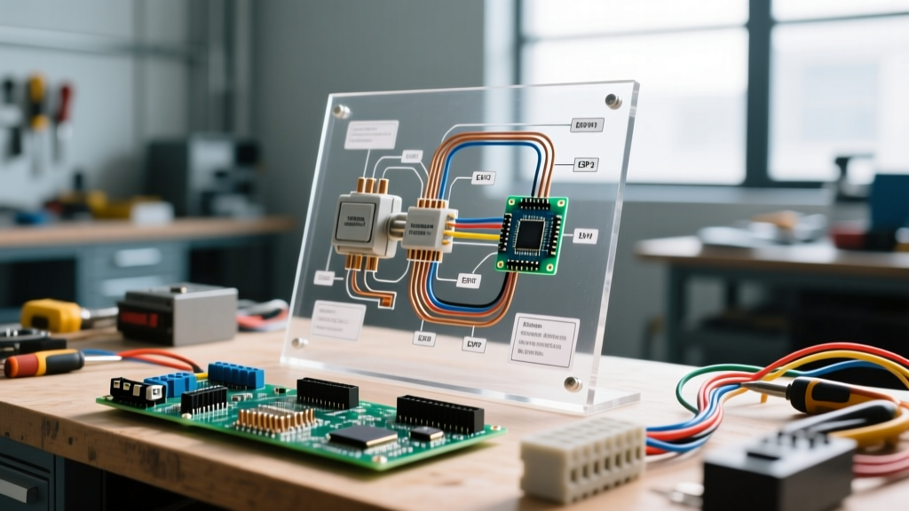
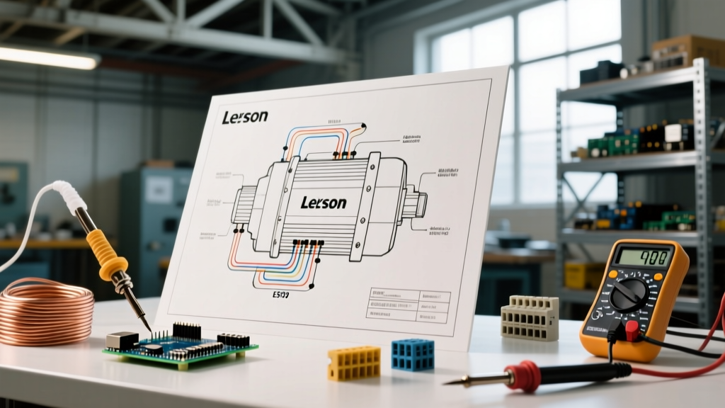
To safely manage this load, you must use a wiring diagram for light bar switch configurations that incorporates a heavy-duty automotive relay. The relay acts as a remote-controlled, high-amperage bridge, allowing your low-amperage dashboard switch to merely "trigger" the circuit while the heavy current flows directly from the battery to the light bar. Below is our comprehensive, 2026-updated step-by-step walkthrough for executing this setup to SAE (Society of Automotive Engineers) standards.
Bill of Materials (BOM) & 2026 Component Guide
Before cutting any wire, gather the correct materials. Skipping marine-grade or automotive-specific components leads to premature corrosion and voltage drop.
| Component | Specification / Model | Purpose | Est. Cost (2026) |
|---|---|---|---|
| Automotive Relay | Bosch-Style ISO Mini 5-Pin (12V, 40A) | High-amperage switching bridge | $8.00 - $12.00 |
| Main Power Wire | 10 AWG Marine-Grade Tinned Copper | Battery to Relay, Relay to Light Bar | $22.00 / 25ft |
| Trigger Wire | 16 AWG GXL Automotive Wire | Switch to Relay trigger circuit | $14.00 / 25ft |
| Inline Fuse Holder | MAXI or ATO Blade Fuse Holder w/ 30A Fuse | Short-circuit protection | $9.50 |
| Fuse Tap | Littelfuse Add-A-Circuit (ATO/ATM) | Switched 12V trigger source | $11.00 |
| Connectors | Deutsch DT 2-Pin & Adhesive Heat Shrink | IP68 waterproof terminations | $18.00 / kit |
Understanding the 5-Pin Relay Pinout
The standard Bosch-style 5-pin relay is the backbone of off-road lighting. According to Hella's automotive electrical guidelines, understanding the DIN 72552 terminal numbering system is critical for proper wiring:
- Pin 30 (Common): 12V+ direct from the battery (Main Power In).
- Pin 87 (Normally Open): 12V+ out to the light bar (Load Out).
- Pin 86 (Coil +): 12V+ trigger from the dashboard switch.
- Pin 85 (Coil -): Ground for the internal electromagnetic coil.
- Pin 87a (Normally Closed): Unused in standard light bar setups (leave capped).
Expert Note: Never use the "Normally Closed" (87a) pin for a standard light bar. If wired incorrectly, the light bar will remain on when the vehicle is off and only turn off when you flip the switch, draining your battery overnight.
Step-by-Step Wiring Walkthrough
Step 1: The Main Power Circuit (Battery to Relay)
- Disconnect the Battery: Always pull the negative terminal first to prevent accidental shorts.
- Measure and Cut: Run your 10 AWG tinned copper wire from the positive battery terminal to your planned relay mounting location (usually inside the engine bay, away from exhaust heat).
- Install the Inline Fuse: Crimp an inline MAXI fuse holder into this wire. Critical Rule: The fuse must be located within 18 inches of the battery positive terminal. If a short occurs between the battery and the relay, this fuse prevents the wire from turning into a red-hot heating element.
- Terminate Pin 30: Crimp a 1/4" female quick-disconnect terminal onto the end of the wire and push it firmly onto Pin 30 of the relay.
Step 2: The Load Circuit (Relay to Light Bar)
- Route to the Light Bar: Run a second length of 10 AWG wire from Pin 87 on the relay to the front grille/bumper where the light bar is mounted.
- Firewall & Chassis Routing: If routing through the engine bay, use split-loom tubing to protect against abrasion. Secure the wire every 12 inches using UV-resistant nylon zip ties, avoiding sharp metal edges.
- Waterproof Connections: At the light bar, do not use cheap spade connectors. Use a Deutsch DT connector. Strip the wire, crimp the solid Deutsch pins using an IWISS IWS-1504M tool, insert them into the housing until they click, and seal the rear with 3M FP-301 adhesive-lined heat shrink to prevent moisture wicking.
Step 3: The Trigger Circuit (Switch to Relay)
This is where most DIYers make mistakes. You need a switched 12V source so the light bar only turns on when the ignition is in the "ACC" or "ON" position.
- Find a Switched Fuse: Use a multimeter to test your interior fuse box. Look for a circuit that reads 0V with the key off, and 12V with the key in ACC (e.g., windshield wipers, 12V accessory socket, or rear defroster). Do not tap into CAN-bus modules, airbags, or ECU fuses.
- Install the Add-A-Circuit: Plug the Littelfuse Add-A-Circuit into the chosen slot. Run 16 AWG GXL wire from the Add-A-Circuit lead up through the firewall to the relay.
- Wire the Dashboard Switch: Run the 16 AWG wire into the cabin and connect it to the "Power" pin on your rocker switch. Run a second 16 AWG wire from the switch's "Load" pin back through the firewall to Pin 86 on the relay.
- Switch Illumination Ground: Most OEM-style rocker switches have a dedicated pin for the LED indicator light. Run a wire from this pin to a clean chassis ground inside the cabin so the switch lights up only when activated.
Step 4: Grounding the Relay and System
A poor ground causes voltage drop, resulting in dim lights and premature relay failure. Run a 16 AWG wire from Pin 85 on the relay to the vehicle chassis. Use a wire brush or sandpaper to remove all paint, powder coating, and rust down to bare, shiny metal. Secure the ring terminal with a stainless steel bolt and apply a dab of dielectric grease over the top to prevent future oxidation.
Wire Gauge & Voltage Drop Matrix
LED light bars are highly sensitive to voltage drop. If your 50-inch bar receives less than 12.5V, the internal constant-current drivers may flicker or shut down entirely. Use the Southwire Voltage Drop Calculator as a baseline, but refer to this matrix for 12V DC automotive applications:
| Total Wire Length (Round Trip) | 10 Amp Load (32" Bar) | 20 Amp Load (50" Bar) | 30 Amp Load (Dual Bars) |
|---|---|---|---|
| Under 10 Feet | 14 AWG | 12 AWG | 10 AWG |
| 10 to 15 Feet | 12 AWG | 10 AWG | 8 AWG |
| 15 to 20 Feet | 10 AWG | 8 AWG | 6 AWG |
Note: Total wire length includes the distance from the battery to the relay, plus the relay to the light bar, plus the ground return path.
Common Failure Modes & Troubleshooting
1. The Switch LED Stays On After Turning Off the Vehicle
The Cause: Modern vehicles (2020 and newer) use Body Control Modules (BCMs) that send low-voltage pulses to check bulb continuity. This micro-current backfeeds through your trigger wire, faintly illuminating the switch LED and potentially keeping the relay partially engaged. The Fix: Install a standard 1N4001 rectifier diode in-line on the trigger wire between the switch and Pin 86. The diode acts as a one-way valve, allowing current to flow to the relay but blocking the BCM's backfeed pulses.
2. Light Bar Flickers at High RPMs
The Cause: This is rarely a light bar issue; it is an alternator ripple or severe voltage drop. If you used 14 AWG wire for a 50-inch bar, the resistance is too high. The Fix: Upgrade the main power and ground runs to 8 AWG or 10 AWG marine-grade wire. Ensure the battery negative terminal is firmly grounded to the engine block.
3. Relay Clicks Rapidly or Chatter Occurs
The Cause: The trigger circuit is not receiving a solid 12V signal, often due to a high-resistance connection at the Add-A-Circuit fuse tap or a loose ground on Pin 85. The Fix: Check the fuse tap orientation. In many modern fuse boxes, the "load" side and "line" side are reversed. If the Add-A-Circuit is plugged in backward, it forces current through the original fuse before reaching your accessory, causing a voltage bottleneck. Pull the tap, test with a multimeter, and flip it 180 degrees if necessary.
Final Safety Inspections
Before reconnecting the battery, perform a visual audit. Verify that no bare copper is exposed outside of heat shrink or connectors. Ensure the 30A inline fuse is securely seated and that the relay is mounted in a dry location, preferably inside a sealed relay harness box. According to Littelfuse automotive safety standards, proper overcurrent protection and environmental sealing are the two primary factors in preventing vehicular electrical fires. Once verified, reconnect the battery, turn the key to ACC, and flip the switch. Your light bar should illuminate instantly, with the dashboard rocker switch glowing cleanly, backed by a safe, robust, and professional-grade wiring harness.