
The Schematic as a Diagnostic Map
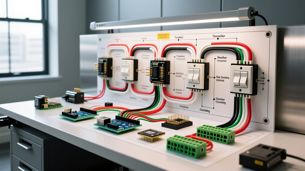
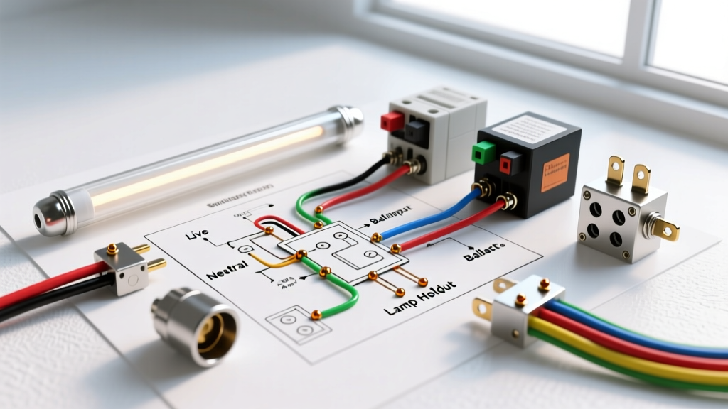
When a fluorescent fixture fails, most DIYers immediately assume the tubes are dead and replace them, only to find the fixture still flickers or remains completely dark. The truth is that the ballast is the brain of the fixture, and the fluorescent light wiring diagram for ballast troubleshooting is your most critical diagnostic map. Rather than viewing the schematic printed on the ballast label merely as an installation guide, electrical professionals use it to isolate faults, verify circuit topology, and prevent catastrophic miswiring during repairs.
As of 2026, while LED retrofits dominate new commercial construction, millions of legacy T8 and T12 fluorescent systems remain in operation in industrial, agricultural, and residential settings. Understanding how to trace the input (line voltage) and output (lamp drive) nodes on these diagrams is essential for accurate multimeter testing and component-level troubleshooting.
Identifying Ballast Topology from the Diagram
Before you touch a multimeter probe to a wire, you must identify the ballast's starting topology. The wiring diagram will visually confirm whether you are dealing with an Instant Start, Rapid Start, or Programmed Start ballast. Misidentifying these will lead to incorrect continuity tests and false diagnostics.
| Topology | Diagram Visual Cues | Output Wire Colors | Common Applications |
|---|---|---|---|
| Instant Start (IS) | Single wire routed to each lamp end; lamps wired in series. | Blue (Output), Red (Output) | Standard 4ft / 8ft T8 commercial troffers |
| Rapid Start (RS) | Two wires routed to each lamp end; continuous filament heating circuit. | Blue/Red (One end), Yellow (Other end) | Dimmable fixtures, older T12 systems |
| Programmed Start (PS) | Two wires per end, but schematic shows a time-delay ignition sequence. | Blue/Red (One end), Yellow (Other end) | Occupancy sensor areas, cold environments |
The High-Frequency Measurement Trap
One of the most common mistakes made when using a fluorescent light wiring diagram for ballast troubleshooting is attempting to measure the output voltage with a standard, low-bandwidth digital multimeter (DMM). Modern electronic ballasts, such as the ubiquitous Keystone KTEB-240-1-TP, operate at high frequencies between 20 kHz and 60 kHz to eliminate visible flicker and improve efficacy.
Expert Warning: A standard $15 hardware store multimeter averages AC waveforms at 50/60 Hz. When exposed to the 40 kHz square-wave output of an electronic ballast, a standard DMM will display wildly inaccurate readings (often showing 30V when the actual RMS voltage is over 250V). Always use a True-RMS meter with a bandwidth exceeding 100 kHz, such as the Fluke 117 or Fluke 87V, when probing ballast output nodes.
Diagnostic Matrix: Mapping Symptoms to Diagram Nodes
Use this matrix to correlate physical symptoms with specific nodes on your ballast's wiring diagram. Always ensure power is disconnected via the breaker panel before performing continuity or resistance tests.
| Symptom | Diagram Node to Trace | Multimeter Test & Expected Result | Probable Failure Mode |
|---|---|---|---|
| Completely Dead (No light, no hum) | Input Node (Black/White/Green) | AC Voltage (Live): 120V or 277V between Black and White. | Tripped breaker, faulty wall switch, or severed line voltage wire. |
| Lamps flicker continuously | Output Node (Blue/Red/Yellow) | Continuity (Power Off): Check resistance across lamp pins. Expect 2Ω - 15Ω. | Open filament in the fluorescent tube or loose tombstone connection. |
| Lamps glow only at the ends | Output Node (Rapid Start Yellow wires) | AC Voltage (Live): Measure high-frequency AC across the yellow output pair. | Failed internal starting capacitor within the ballast; ballast cannot generate strike voltage. |
| Loud 60Hz Humming | Physical Chassis / Input Node | Visual/Audio: Magnetic ballasts vibrate due to loose laminations. | Magnetic ballast end-of-life. Replace with an electronic equivalent. |
Real-World Case Study: Philips Advance RELB-4S40-NTP
Let's apply the diagram to a specific, widely used model: the Philips Advance RELB-4S40-NTP. This is a 4-lamp, 40W T12/T8 rapid-start electronic ballast. In 2026, replacement units for this specific model typically cost between $24 and $28.
Tracing the Thermal Protector
If you are troubleshooting this specific ballast and your diagram shows proper 120V input at the black and white wires, but zero voltage at the blue/red output nodes, the internal thermal fuse has likely tripped. The wiring diagram for the RELB series routes the line voltage through an internal thermal switch before it reaches the inverter circuit. If the fixture was installed in an unventilated drop-ceiling where ambient temperatures exceeded 165°F (74°C), the thermal protector opens the circuit permanently to prevent a fire. The diagram confirms that if input voltage is present at the wire nuts but absent internally, the ballast must be replaced; it is not field-serviceable.
Tombstone Shunting: The Silent Ballast Killer
A critical aspect of reading the fluorescent light wiring diagram for ballast repair involves the lamp holders (tombstones). The diagram will dictate whether the tombstones must be shunted or non-shunted.
- Instant Start Diagrams: Require shunted tombstones. The diagram will show a single output wire connecting to the tombstone, which internally bridges the two pins of the fluorescent tube to complete the circuit.
- Rapid/Programmed Start Diagrams: Require non-shunted tombstones. The diagram will show two distinct wires (e.g., one blue, one red) entering the same tombstone. These wires must remain isolated to independently heat each filament pin.
The Edge Case: If a DIYer replaces a broken non-shunted tombstone with a shunted one on a Rapid Start circuit, the moment power is applied, the ballast's high-voltage output is dead-shorted through the tombstone's internal bridge. This instantly blows the ballast's internal output fuse. The wiring diagram is your only defense against this $30 mistake. Always verify the internal continuity of your tombstones with a multimeter before wiring them to the ballast outputs.
When to Abandon the Ballast: LED Type B Retrofit
Given the rising cost of commercial electricity and the phase-out of T12/T8 fluorescent tubes, many electricians use the existing fluorescent light wiring diagram to plan a Type B (Ballast Bypass) LED retrofit. Instead of troubleshooting a failing ballast, you use the diagram to identify the line-voltage input wires (Black/White) and route them directly to the tombstones, completely removing the ballast from the circuit.
When executing a Type B retrofit based on the original schematic:
- Cut the line voltage (Black/White) and output wires (Blue/Red/Yellow) close to the ballast.
- Remove the ballast entirely to eliminate parasitic weight and phantom power draw.
- Wire the 120V/277V line voltage directly to the non-shunted tombstones at one end of the fixture (for single-ended LED tubes).
- Cap off the wires at the opposite end of the fixture.
Safety Protocols and Code Compliance
Troubleshooting live fluorescent circuits exposes you to both standard line voltage (up to 480V in some commercial 3-phase panels) and high-frequency, high-voltage ballast outputs capable of delivering painful shocks. Always adhere to OSHA electrical safety guidelines regarding lockout/tagout (LOTO) procedures before opening any luminaire chassis.
Furthermore, any rewiring or ballast replacement must comply with the National Fire Protection Association (NFPA) NEC Article 410, which governs luminaire wiring, specifically regarding the use of proper wire nuts, high-temperature rated wire (minimum 90°C), and ensuring the equipment grounding conductor is securely bonded to the metal fixture housing to prevent shock hazards in the event of a ballast insulation failure.
Final Diagnostic Checklist
Before closing the fixture lens, verify the following against your specific wiring diagram:
- All wire nuts are twisted tight with no exposed copper strands.
- The grounding wire (Green/Bare) is firmly attached to the chassis ground screw.
- Lamp pins are fully seated and twisted into the tombstones to ensure internal contact.
- The ballast label (and its diagram) is facing downward, visible for the next technician who services the fixture.