
Understanding the Trailer Wiring Diagram for Electric Brakes
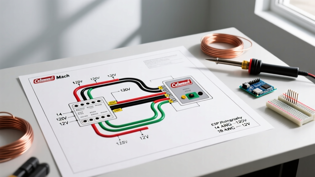
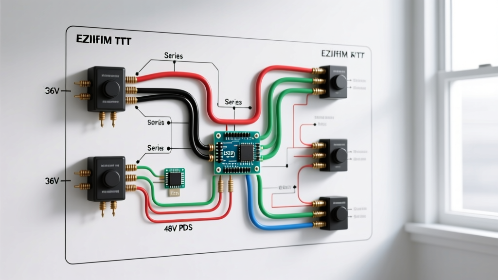
When towing a trailer with a Gross Vehicle Weight Rating (GVWR) over 3,000 pounds, electric brakes are not just a recommendation—they are a legal and safety requirement in most jurisdictions. The backbone of this system is the 7-way RV blade connector, governed by the SAE J286 standard. A proper trailer wiring diagram electric brakes setup ensures that your tow vehicle's brake controller can seamlessly communicate with the trailer's brake magnets, while simultaneously powering running lights, turn signals, and the critical breakaway system.
In 2026, with the rise of heavier lithium-powered travel trailers and dual-axle car haulers, the electrical load on the 7-way connector is higher than ever. Relying on outdated 12 AWG wire for brake circuits or using generic 'scotch-lock' connectors are primary causes of voltage drop, resulting in weak braking performance or complete system failure. This comprehensive reference guide breaks down the exact pinouts, wire gauge requirements, and diagnostic procedures for wiring electric trailer brakes.
The SAE J286 7-Way RV Blade Pinout Diagram
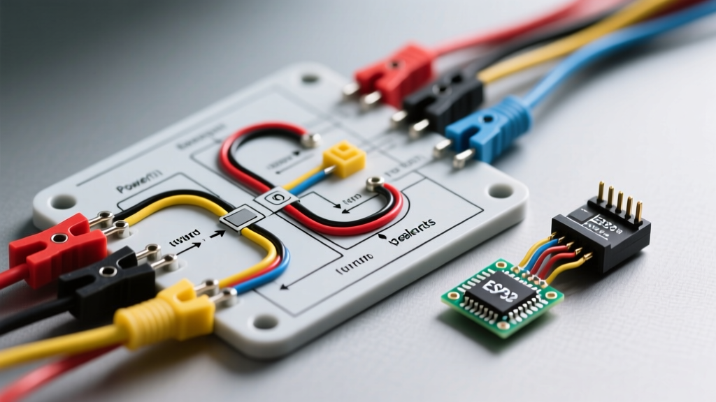
The 7-way RV blade is the undisputed industry standard for trailers equipped with electric brakes. Below is the definitive pinout reference for both the tow vehicle (female receptacle) and the trailer (male plug). Note that wire colors are standardized, but you must always test with a multimeter, as previous owners or aftermarket repairs may have deviated from the norm.
| Pin Position | Wire Color | Function | Recommended AWG | Max Amperage |
|---|---|---|---|---|
| 1 (Bottom Center) | White | System Ground | 8 AWG or 6 AWG | 40A+ |
| 2 (Top Right) | Black | 12V Auxiliary / Battery Charge | 10 AWG | 30A - 40A |
| 3 (Top Left) | Yellow | Reverse Lights / Auxiliary | 12 AWG | 15A |
| 4 (Mid Right) | Red | Left Turn / Stop Lights | 12 AWG | 15A |
| 5 (Mid Left) | Green | Right Turn / Stop Lights | 12 AWG | 15A |
| 6 (Bottom Right) | Brown | Tail / Running / Marker Lights | 12 AWG | 15A |
| 7 (Bottom Left) | Blue | Electric Brakes Output | 10 AWG | 20A - 30A |
Electric Brake Controller Integration & The Breakaway System
The Blue wire (Pin 7) is the dedicated circuit for the electric brakes. It carries the modulated DC voltage from the tow vehicle's brake controller (such as the highly rated Tekonsha Prodigy P3 or the Redarc Tow-Pro Elite V2) directly to the trailer's brake magnets. When you apply the vehicle's brakes, the controller sends a proportional voltage (ranging from 2V for light braking up to 12V for emergency stops) down this blue wire.
The Breakaway Switch: A Critical Safety Intersect
A vital component often misunderstood in trailer wiring diagrams is the breakaway switch. This device is mounted on the trailer tongue and features a lanyard pinned to the tow vehicle's bumper or hitch. If the trailer physically detaches, the pin pulls out, triggering the switch.
- Power Source: The breakaway switch must be wired to a dedicated 12V source. This is typically the trailer's onboard breakaway battery, or it can be tapped into the Black wire (Pin 2) coming from the tow vehicle, provided a 40A auto-reset circuit breaker (like the Bussmann CB181-40) is installed within 18 inches of the vehicle battery.
- Output: The output side of the breakaway switch splices directly into the Blue wire on the trailer side. When triggered, it bypasses the brake controller and sends a full, unmodulated 12V directly to the brake magnets, locking the trailer wheels to prevent a runaway situation.
Expert Warning: Never wire the breakaway switch to the running lights (Brown wire) or the auxiliary 12V line without an inline breaker. If a short occurs during a breakaway event, it will blow the tow vehicle's main fuse, disabling the brakes entirely when you need them most.
Wire Gauge Selection & Voltage Drop Matrix
Electric brake magnets draw significant current. A standard 10-inch Dexter Nev-R-Lube brake magnet draws roughly 3.0 to 3.5 amps at 12V. A dual-axle trailer with four magnets will pull 12 to 14 amps continuously during hard braking. Because trailers are long, voltage drop over the distance of the wire run is a major factor. Using 12 AWG wire for a 25-foot run to a dual-axle trailer will result in a voltage drop of nearly 2 volts, meaning your rear brakes only receive 10V, leading to uneven braking and premature magnet wear.
| Trailer Length (Round Trip Run) | Number of Axles (Magnets) | Peak Amperage Draw | Minimum Required Wire Gauge (Blue Wire) |
|---|---|---|---|
| Up to 15 Feet | Single (2 Magnets) | 7A - 8A | 12 AWG (10 AWG Preferred) |
| 15 to 25 Feet | Single (2 Magnets) | 7A - 8A | 10 AWG |
| Up to 20 Feet | Tandem (4 Magnets) | 14A - 16A | 10 AWG |
| 20 to 35 Feet | Tandem (4 Magnets) | 14A - 16A | 8 AWG |
| Any Length | Triple (6 Magnets) | 21A - 24A | 8 AWG or 6 AWG |
Step-by-Step Wiring & Termination Procedure
To ensure a weatherproof and vibration-resistant connection, follow this professional termination workflow:
- Strip and Clean: Strip exactly 3/8 inch of insulation from the bonded trailer wire. Do not nick the copper strands, as this creates a weak point for fatigue failure.
- Use Adhesive-Lined Heat Shrink Terminals: Avoid standard vinyl crimp connectors. Use nylon or polyolefin adhesive-lined heat shrink ring terminals (e.g., 12-10 AWG size). The internal sealant melts during heating, creating a waterproof barrier against road salt and moisture.
- Crimp and Solder (Optional but Recommended): Use a ratcheting crimp tool (like the Titan 11230) to ensure a uniform, gas-tight crimp. For high-vibration environments, flow a small amount of rosin-core solder into the crimp barrel after crimping.
- Apply Dielectric Grease: Before mating the 7-way male plug to the vehicle's female receptacle, apply a liberal amount of dielectric tune-up grease (such as Permatex 22058) to the pins. This prevents galvanic corrosion between the brass pins and the copper wire.
- Secure the Umbilical Cord: Use a coiled cable support or a heavy-duty bungee to ensure the 7-way cable has enough slack for tight turns but cannot drag on the pavement if it disconnects from the receptacle.
Diagnostic Troubleshooting Matrix
When your electric brakes fail to engage or lock up unexpectedly, use a digital multimeter (DMM) to isolate the fault. Set your DMM to DC Volts for voltage tests, and Ohms for continuity tests.
| Symptom | Probable Cause | Multimeter Diagnostic Test |
|---|---|---|
| Brakes lock up when headlights are turned on. | Short between Brown (Tail) and Blue (Brake) wires, or poor White ground causing backfeed. | Disconnect trailer. Measure resistance between Blue and Brown pins on trailer plug. Should read 'OL' (Open Loop). If near 0 Ohms, locate short. |
| Brake controller shows 'S.H.' or 'OL' error. | Open circuit in the Blue wire, disconnected magnet, or blown inline fuse. | Measure resistance between Blue pin and White pin on trailer plug. A healthy 2-magnet system should read 3.0 to 4.0 Ohms. 'OL' means a broken wire. |
| Weak braking; controller outputs 12V but trailer brakes barely engage. | Severe voltage drop due to undersized wire, corroded pins, or failing ground. | With trailer connected and manual override depressed, probe the Blue wire at the trailer axle junction box. If voltage is below 10.5V, you have a voltage drop issue in the harness. |
| Breakaway system fails to lock brakes during test. | Dead breakaway battery, corroded switch contacts, or blown 40A breaker. | Pull breakaway pin. Measure DC voltage at the Blue wire inside the trailer junction box. Must read a minimum of 11.5V. If 0V, test switch continuity. |
Authoritative References & Standards
For further technical specifications, safety regulations, and product-specific wiring schematics, consult the following industry authorities:
- SAE International: The SAE J286 standard dictates the physical dimensions and pin assignments for the 7-way connector. Refer to the SAE Mobility Engineering Portal for standardized automotive electrical guidelines.
- eTrailer Wiring Database: For vehicle-specific tow package wiring and adapter schematics, the eTrailer Wiring FAQ remains the most comprehensive, up-to-date database for both OEM and aftermarket harness integrations.
- Tekonsha / Lippert Resources: For exact brake controller wiring diagrams, proportional sensor calibration, and magnet resistance charts, consult the official Tekonsha Installation Guides.
- NHTSA Towing Safety: The National Highway Traffic Safety Administration provides federal guidelines on towing capacities, breakaway system requirements, and trailer lighting mandates.
By strictly adhering to this trailer wiring diagram for electric brakes, utilizing the correct 10 AWG or 8 AWG wire for high-current circuits, and executing professional-grade terminations, you ensure maximum stopping power and highway safety for your rig.