
Strategic Planning for 3 Phase Electrical Wiring Installations
Transitioning a facility, heavy-duty workshop, or commercial space to 3 phase electrical wiring is a major infrastructure investment that unlocks higher power density, improved motor efficiency, and balanced load distribution. Unlike single-phase systems that pulse power delivery, three-phase systems provide a continuous, smooth flow of electricity, making them the undisputed standard for heavy machinery, commercial HVAC, CNC equipment, and modern EV fleet charging stations.
However, planning a 3 phase electrical wiring installation requires rigorous adherence to the National Electrical Code (NEC), precise load calculations, and an understanding of phase topologies. This guide provides a comprehensive, expert-level planning framework for electricians and facility managers navigating 3-phase upgrades in 2026, complete with specific equipment recommendations, wire sizing matrices, and real-world cost expectations.
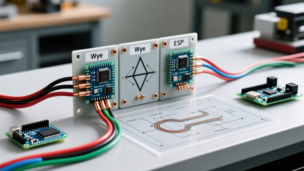
Wye (Y) vs. Delta (Δ) Configurations: Choosing the Right Topology
The first critical decision in your installation plan is selecting the correct transformer and service topology. The choice between Wye and Delta configurations dictates your available voltages, neutral requirements, and grounding strategies.
| Configuration | Standard Voltages (US) | Neutral Availability | Primary Use Cases |
|---|---|---|---|
| Wye (Y) | 208Y/120V or 480Y/277V | Yes (Center-point grounded) | Commercial buildings, IT data centers, mixed lighting/power loads. |
| Delta (Δ) | 240V or 480V | No (Ungrounded or Corner-grounded) | Industrial manufacturing, heavy motor loads, water treatment plants. |
| High-Leg Delta | 240V (with 208V high leg) | Yes (Center-tap on one phase) | Legacy industrial sites needing both 240V 3-phase and 120V single-phase. |
Handling High-Leg Delta Systems
If your facility utilizes a 240V High-Leg (or Red-Leg) Delta system, extreme caution is required during panel termination. The high leg (typically Phase B) yields 208V to ground rather than 120V. Per NEC 110.15, the high-leg conductor must be durably marked with an orange outer finish or tagged effectively to prevent catastrophic equipment failure from accidental 120V line-to-neutral connections.
NEC-Compliant Wire Sizing and Conduit Fill Calculations
Proper conductor sizing for 3 phase electrical wiring hinges on the equipment's full-load ampacity (FLA), terminal temperature ratings, and ambient temperature corrections. Most modern 3-pole breakers and motor starters feature 75°C rated terminals. Therefore, while THHN/THWN-2 wire is rated for 90°C in the conduit, the allowable ampacity must be derived from the 75°C column of NEC Table 310.16.
Copper Conductor Sizing Matrix (75°C Column, 3 Current-Carrying Conductors)
| Breaker Size (Amps) | Min. Copper AWG/kcmil | Min. EMT Conduit Size | Typical Application |
|---|---|---|---|
| 30A | 10 AWG | 1/2 inch | Small HVAC compressors, 5HP motors |
| 60A | 6 AWG | 3/4 inch | Commercial EV Level 2 chargers, 15HP motors |
| 100A | 3 AWG | 1 inch | Small CNC machines, workshop subpanels |
| 200A | 3/0 AWG | 1.5 inch | Industrial main feeders, large RTU HVAC units |
| 400A | 600 kcmil | 2.5 inch | Heavy manufacturing main switchboards |
Expert Tip: Voltage Drop on Long Runs
For feeder runs exceeding 100 feet, voltage drop becomes a critical factor. While the NEC recommends a maximum 3% drop for feeders (and 5% total combined with branch circuits), 3-phase motor starting currents (LRA) can cause severe dimming or contactor chatter if the drop is too high. Always upsize conductors by at least one gauge for runs over 150 feet, or utilize XHHW-2 wire in underground PVC conduit to maximize thermal dissipation.
Panelboard and Breaker Selection: 2026 Market Standards
Selecting the right overcurrent protection devices (OCPD) ensures both safety and operational continuity. In 2026, the market has shifted heavily toward molded case circuit breakers (MCCBs) with adjustable trip settings for commercial 3-phase applications, allowing facility managers to dial in exact coordination curves.
Recommended Equipment & Estimated 2026 Costs
- Eaton FD3060 (60A 3-Pole MCCB, 600V Class): Ideal for branch circuit protection. Features a high interrupting capacity (65kAIC at 480V). Estimated Cost: $380 - $450.
- Square D PowerPact H-Frame (e.g., HJP36150): Excellent for main feeder protection up to 150A. Includes electronic trip units for precise ground-fault and short-circuit tuning. Estimated Cost: $1,200 - $1,600.
- Schneider Electric NF Panelboard (480Y/277V): A bolt-on, heavy-duty commercial panelboard. Fully rated for industrial environments with copper busbars standard. Estimated Cost: $1,800 - $2,500 (enclosure and interior).
Step-by-Step Installation Sequence & Safety Lockouts
Executing the physical installation of 3 phase electrical wiring demands a strict sequence to prevent phase-to-phase faults and ensure personnel safety. Follow this standardized workflow:
- Utility Coordination & Transformer Sizing: Work with the local utility to install the necessary pad-mounted or pole-top transformer. A typical 150 kVA padmount upgrade costs between $4,500 and $9,000 in 2026, depending on trenching and local co-op fees.
- Conduit Rough-In & Pulling: Install EMT or Rigid Metal Conduit (RMC) for physical protection. Use a dedicated wire-pulling compound (like Polywater J) to reduce friction when pulling 3/0 AWG or larger 3-phase conductors.
- LOTO & Termination: Apply Lockout/Tagout (LOTO) procedures per OSHA electrical safety standards. Terminate phases L1, L2, and L3 in strict sequence. Torque all lug connections to the manufacturer's exact inch-pound specifications using a calibrated torque wrench.
- Phase Rotation Verification: Never energize a 3-phase motor or HVAC compressor without testing rotation. Use a phase rotation meter (such as the Fluke 9040) to verify the L1-L2-L3 sequence matches the equipment's requirement. Reversing the phase sequence on a scroll compressor can destroy the unit in under 10 seconds.
- Energization & Thermal Imaging: Energize the system under no-load, then apply the load. After 45 minutes of operation, scan all panel terminations with an infrared thermal camera (e.g., Fluke TiS60+). Any termination showing a temperature rise greater than 15°F above ambient indicates a loose connection requiring immediate de-energization and re-torquing.
Edge Cases: VFD Harmonics and Oversized Neutrals
Modern industrial facilities rely heavily on Variable Frequency Drives (VFDs) like the ABB ACS580 or Yaskawa GA800 to control 3-phase motor speeds. However, the rectifier front-ends of these drives introduce severe non-linear harmonic distortion back into the 3 phase electrical wiring system.
Mitigating Harmonic Distortion
When planning your wiring for VFD-heavy environments, you must account for these harmonics. Standard transformers will overheat due to eddy currents generated by triplen harmonics (3rd, 9th, 15th). To resolve this:
- Specify K-Rated Transformers: Use a K-13 or K-20 rated isolation transformer. These feature heavier gauge core steel and electrostatic shields designed to dissipate harmonic heat.
- Oversize the Neutral Conductor: In 208Y/120V Wye systems feeding non-linear loads (like LED drivers and IT server racks), triplen harmonics add arithmetically on the neutral bus. Per NEC 310.15(G), the neutral conductor must be sized to carry the maximum unbalanced load, which in modern data-center or office environments often requires a 200% neutral (e.g., using a 500 kcmil neutral for 3/0 AWG phase conductors).
- Install Line Reactors: Place a 3% or 5% impedance line reactor on the input side of every VFD to smooth the incoming sine wave and protect the drive's internal DC bus capacitors from voltage spikes.
Authoritative References and Further Reading
For continuous compliance and advanced engineering data, consult the following industry standards:
- National Fire Protection Association (NFPA 70): The definitive source for all conductor ampacity, conduit fill, and grounding requirements. Access the National Electrical Code (NEC) resources here.
- Fluke Corporation: For practical field-testing methodologies, including phase rotation and power quality analysis, review the Fluke guide to three-phase electrical systems.
- OSHA Electrical Safety: Ensure your installation team complies with federal lockout/tagout and arc-flash boundary requirements via the OSHA Electrical Safety portal.
By meticulously planning your topology, respecting NEC sizing tables, and accounting for modern harmonic edge cases, your 3 phase electrical wiring installation will deliver decades of reliable, high-efficiency power distribution.