
Integrating Car Audio into High-Voltage Motor Platforms
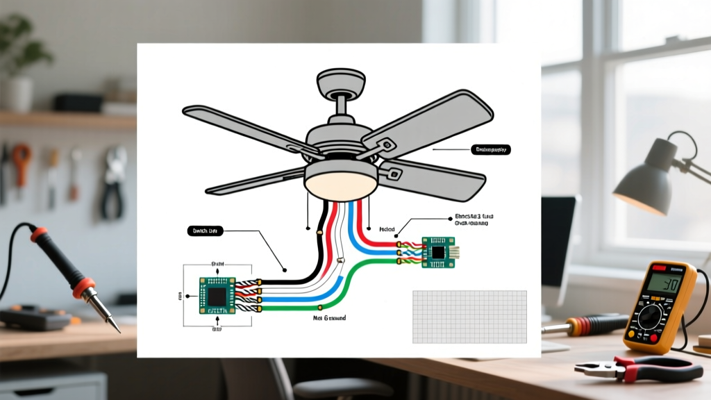
When converting a gas-powered golf cart to an electric drivetrain, building a custom 48V UTV, or outfitting a marine vessel with high-torque DC motors, integrating standard 12V accessories presents a unique electrical challenge. Car audio enthusiasts frequently search for a wiring diagram for JVC radio head units, assuming the process mirrors a standard passenger vehicle installation. However, when your audio system shares a chassis with high-amperage motor controllers, PWM (Pulse Width Modulation) inverters, and series-wired battery banks, standard automotive wiring practices will lead to catastrophic failures, severe alternator-style whine, or destroyed battery banks.
In this motor wiring tutorial, we bridge the gap between high-voltage EV drivetrains and 12V infotainment. We will dissect the standard JVC 16-pin ISO harness, map it to a DC-DC step-down architecture, and provide actionable EMI (Electromagnetic Interference) suppression techniques to ensure your JVC KD-X or KW-M series head unit delivers pristine audio without disrupting your motor controller logic.
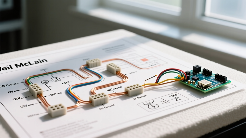
Decoding the Wiring Diagram for JVC Radio Harnesses
Modern JVC head units, such as the popular KD-X280BT digital media receiver or the KW-M560BT multimedia player, utilize a standardized 16-pin ISO connector for power and speaker outputs. Before adapting this to a motorized platform, you must understand the baseline pinout. Misrouting the constant 12V and switched 12V lines in an off-road vehicle is the number one cause of parasitic battery drain.
| Wire Color | Function | Motor Platform Adaptation |
|---|---|---|
| Yellow | Constant 12V (Memory) | Connect to the regulated 12V output of your DC-DC converter. |
| Red | Switched 12V (Ignition) | Connect to the motor controller key-switch relay or a secondary low-current DC-DC trigger. |
| Black | Ground | Must be tied to a dedicated, clean chassis ground or isolated DC-DC negative terminal. |
| Blue/White | Remote Turn-On (Amp) | Use to trigger external amplifiers; keep away from PWM motor signal wires. |
| Orange/White | Illumination | Optional; tie to the dash lighting circuit if your custom UTV dash supports it. |
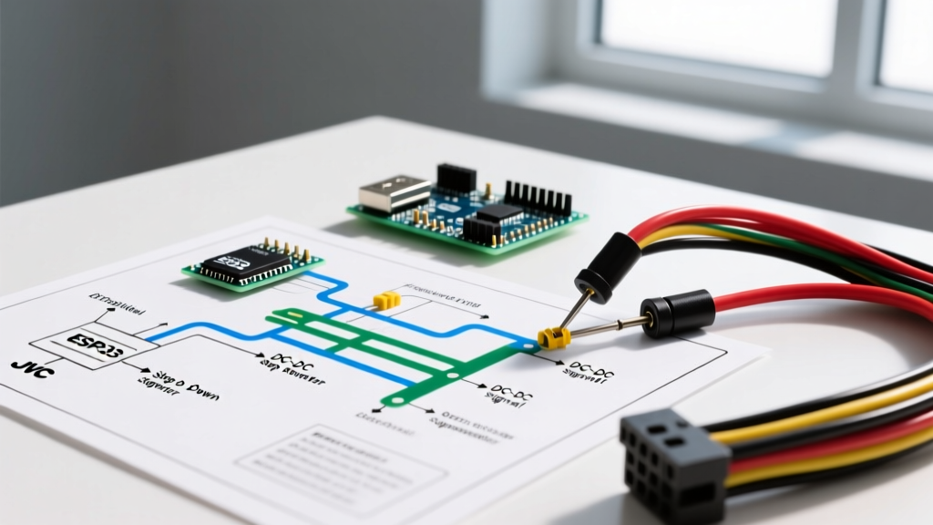
The Motor Wiring Bridge: 48V/36V to 12V Step-Down
The most critical mistake DIYers make when following a standard automotive wiring diagram for JVC radio units in a golf cart is tapping directly into a single 8V or 12V battery within a 36V or 48V series-wired lead-acid or lithium string. According to guidelines referenced by the NFPA 70 National Electrical Code regarding balanced DC loads, drawing uneven current from a series battery bank causes severe voltage imbalance. This leads to localized sulfation in lead-acid batteries or triggers the BMS (Battery Management System) to shut down a lithium pack.
Critical Warning: Never wire a 12V radio directly to one battery in a 48V golf cart pack. You will destroy an $800+ battery bank within a few months. You must use an isolated DC-DC step-down converter.
Sizing Your DC-DC Converter for Audio Loads
To safely step down 36V-72V motor pack voltage to the 12V required by the JVC harness, you need a heavy-duty switching DC-DC converter. A standard JVC head unit draws roughly 10A-15A at peak volume. If you are also powering a marine-grade amplifier or illuminated rock lights, your draw will increase.
- Head Unit Only: 15A (180W) Continuous DC-DC Step-Down Converter. (Cost: ~$35 - $45)
- Head Unit + 4-Channel Amp: 30A (360W) Converter with integrated heat sink and cooling fan. (Cost: ~$60 - $85)
- Wire Gauge Requirements: Use 10 AWG wire for the 48V input side of the converter, and 12 AWG wire for the 12V output side running to the radio harness. Always install an inline ATC fuse rated 25% higher than your max draw on the input side.
Suppressing PWM Motor Controller EMI and Whine
Electric UTVs and golf carts use high-amperage PWM motor controllers (like those from Alltrax or Curtis) to regulate speed. These controllers switch DC voltage on and off at frequencies typically ranging from 8kHz to 16kHz. This rapid switching generates massive Electromagnetic Interference (EMI). If your JVC radio's RCA cables or power wires run parallel to the motor phase cables, this EMI will induce a high-pitched whine into your audio system that changes pitch with motor RPM.
The FCC Electromagnetic Compatibility Division outlines strict parameters for mitigating radiated emissions in DC motor environments. To adapt these principles to your JVC radio installation, follow these routing and filtering rules:
1. Physical Separation and Routing
Never run your 12V JVC power harness or RCA audio cables in the same wire loom or conduit as the thick motor phase cables (U, V, W phases). Maintain a minimum physical separation of 12 inches. If the wires must cross, ensure they cross at a strict 90-degree angle to minimize inductive coupling.
2. Implementing LC Filters and Ferrite Chokes
If physical separation is impossible due to chassis constraints, you must filter the power. Install an inline LC (Inductor-Capacitor) noise filter on the 12V constant power line immediately before it connects to the JVC yellow wire. Additionally, snap ferrite bead chokes onto the RCA cables as close to the head unit's rear chassis as possible. These components absorb high-frequency PWM noise before it reaches the radio's internal pre-amp.
3. Establishing a Star Ground Topology
Ground loops are the primary culprit of static in motorized audio setups. Do not daisy-chain your grounds. Run the black ground wire from the JVC harness, the ground from your DC-DC converter, and the ground from your external amplifier all to a single, centralized grounding bus bar. From that bus bar, run a single, heavy-gauge (4 AWG) cable directly to the negative terminal of the main battery bank. This 'star ground' topology ensures that high-current motor return spikes do not modulate the audio ground reference.
Step-by-Step Execution Guide
- Disconnect the Main Pack: Always disconnect the main negative terminal of your 36V/48V motor battery bank before cutting or splicing any wires.
- Mount the DC-DC Converter: Secure the step-down converter to a metal chassis point for heat dissipation. Connect the 48V input using 10 AWG wire and an inline fuse.
- Wire the Ignition Trigger: Locate the 12V key-switch output on your motor controller. Connect this to the Red (Switched) wire on the JVC harness so the radio only powers on when the vehicle is keyed to 'ON'.
- Map the ISO Harness: Using the wiring diagram for JVC radio pinouts provided above, connect the Yellow (Constant) and Black (Ground) wires to the output side of your DC-DC converter.
- Route Speaker Wires: Use 14 AWG oxygen-free copper (OFC) speaker wire. Route these wires along the opposite side of the vehicle's frame from the motor controller and throttle cables.
- Test and Verify: Reconnect the main battery. Turn the key to the ON position. Use a digital multimeter to verify the DC-DC converter is outputting a stable 13.8V to 14.4V before plugging the harness into the back of the JVC head unit.
Frequently Asked Questions
Can I use a linear voltage regulator instead of a switching DC-DC converter?
No. Linear regulators (like the LM317) dissipate excess voltage as heat. Stepping down 48V to 12V at 10 amps using a linear regulator would generate roughly 360 watts of pure heat, instantly destroying the component and posing a severe fire hazard. Always use a high-efficiency switching buck converter (typically 90-95% efficient) for motor platform audio wiring.
My JVC radio turns on, but the display resets every time I accelerate the motor. Why?
This is a classic voltage sag issue. When the motor controller demands high amperage for acceleration, the main battery pack voltage drops. If your DC-DC converter has a low-voltage cutoff or cannot maintain 12V under heavy input sag, the JVC head unit will brown out and reboot. Upgrade to a DC-DC converter with a wider input voltage tolerance (e.g., 30V-60V) and ensure your main battery bank is healthy and fully charged. For more official specifications on power requirements, consult the JVC Car Entertainment support documentation for your specific model.
Does the JVC remote turn-on wire (Blue/White) need a relay?
If you are only powering the head unit, no. However, if you are using the Blue/White wire to trigger a high-draw marine amplifier or a motorized antenna, the JVC internal circuit can only supply about 200mA. You must use this wire to trigger a standard 12V automotive relay, which will then switch the high-current power required by your external accessories.