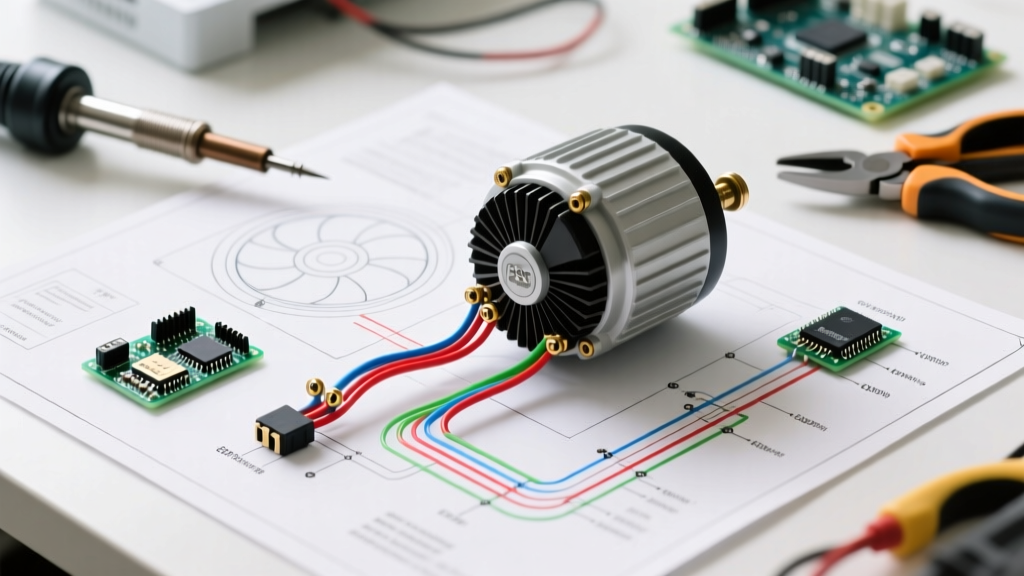

Decoding the Electric Fan Wiring Schematic: A Motor Wiring Tutorial
Whether you are retrofitting a legacy residential air handler or commissioning a commercial exhaust system, understanding an electric fan wiring schematic is the foundational skill of HVAC and industrial motor maintenance. As of 2026, the industry has largely transitioned from simple Permanent Split Capacitor (PSC) motors to advanced Electronically Commutated Motors (ECM) driven by stringent Department of Energy (DOE) efficiency mandates. However, millions of PSC motors remain in the field, and technicians must be fluent in both schematic types to troubleshoot effectively.
This tutorial provides a deep-dive into reading, interpreting, and executing field wiring for both PSC and ECM fan motors, complete with wire color standards, terminal pinouts, and safety protocols aligned with modern electrical codes.
Anatomy of a Standard Fan Motor Schematic
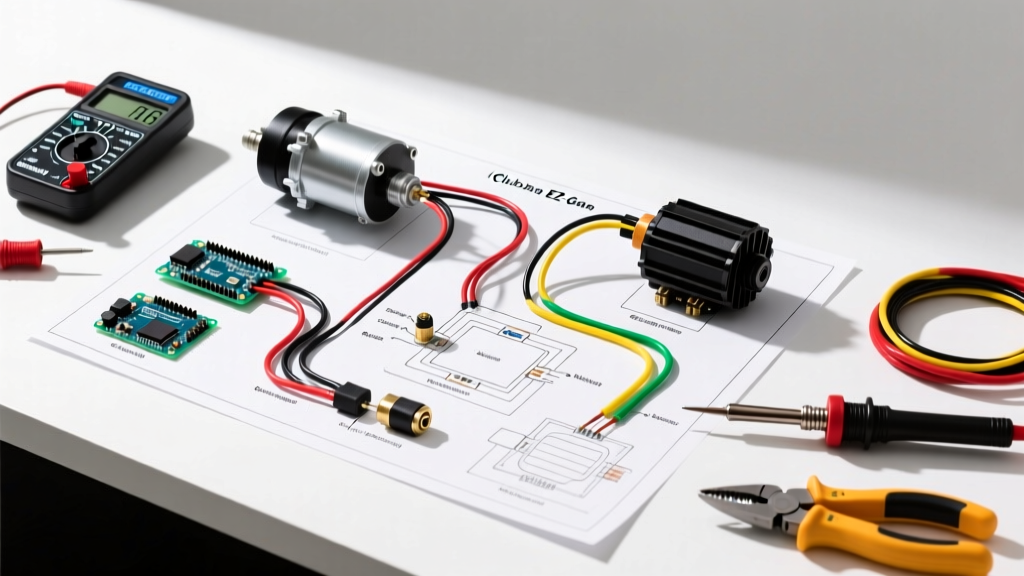
Before making any physical connections, you must be able to read the schematic diagram typically glued to the motor housing or included in the OEM installation manual. An electric fan wiring schematic translates the internal electromagnetic windings into a logical map.
Key Schematic Symbols to Recognize
- Zig-Zag Lines: Represent the motor windings (Run and Start windings). In a PSC motor, the start winding remains in the circuit during operation.
- Parallel Plates: The run capacitor, measured in microfarads (µF or MFD). It creates the phase shift necessary to generate starting torque.
- Bimetallic Switch Symbol: The internal thermal overload protector. If the motor exceeds its thermal limit (usually around 265°F / 129°C for Class B insulation), this switch opens the circuit to prevent a fire.
- Tap Points (T1, T2, T3): Indicate multi-speed settings by altering the active resistance of the run winding.
Wiring a PSC Motor: The Fasco A136 Blueprint
The Permanent Split Capacitor (PSC) motor remains the workhorse of older residential HVAC systems and light commercial exhaust fans. Let us examine the wiring logic for a highly common replacement motor: the Fasco A136 (1/4 HP, 1050 RPM, 115V, 60Hz).
When interpreting the electric fan wiring schematic for a standard 3-speed PSC motor, you will typically encounter a 5-wire or 6-wire harness. The most critical mistake novices make is misidentifying the capacitor wires, which can instantly destroy the motor windings upon energization.
Standard PSC Wire Color Chart & Function
| Wire Color | Function | Termination Point |
|---|---|---|
| White | Common (Neutral) | Connected to Line 2 (Neutral) AND one side of the contactor/relay. |
| Black | High Speed | Connected to Line 1 (Hot) via the fan relay or contactor. |
| Blue | Medium Speed | Unused (insulated and tucked away if High speed is selected). |
| Red | Low Speed | Unused (insulated and tucked away if High speed is selected). |
| Brown | Capacitor Lead 1 | Connected exclusively to one terminal of the run capacitor. |
| Brown w/ White Stripe | Capacitor Lead 2 | Connected exclusively to the other terminal of the run capacitor. |
Crucial Note: Never connect the brown capacitor wires to line voltage. The run capacitor (typically 5 MFD / 370VAC for a 1/4 HP motor) must be wired in series with the start winding. If your schematic shows a jumper wire from the Common (White) to the capacitor, it is because the internal wiring requires the neutral reference to complete the phase-shift circuit. Always follow the specific diagram on your motor's belly band.
The Modern Standard: ECM Motor Schematics (Genteq X13)
Driven by the DOE's updated energy conservation standards for commercial fans and blowers, the industry has aggressively adopted ECM technology. The Genteq X13 (now manufactured under the Regal Rexnord umbrella) is the dominant fractional-horsepower ECM in modern air handlers. Unlike the PSC motor, the ECM schematic is divided into two completely isolated circuits: High Voltage (Power) and Low Voltage (Control).
High-Voltage Power Connections (3-Pin Plug)
The high-voltage side is straightforward but demands strict adherence to grounding standards per NEMA MG-1 guidelines.
- Pin 1 (L / Black): 120VAC or 240VAC Line (Hot). This provides continuous power to the motor's internal inverter.
- Pin 2 (N / White): Neutral return.
- Pin 3 (G / Green): Earth Ground. Never omit this ground. The ECM's internal logic board is highly susceptible to static discharge and voltage transients; a missing ground will lead to premature board failure.
Low-Voltage Control Connections (5-Pin Plug)
The 5-pin connector receives 24VAC signals from the HVAC control board to dictate motor speed and operation. The schematic will map these pins as follows:
- Pin 1 (C / Common): 24VAC Common from the transformer.
- Pin 2 (G / Fan): Energizes the motor at the programmed 'Fan Only' speed (usually 30-50% airflow).
- Pin 3 (Y / Compressor): Energizes cooling speed (usually 70-80% airflow).
- Pin 4 (W / Heat): Energizes heating speed (usually 40-50% airflow to prevent cold drafts).
- Pin 5 (EH / Electric Heat): Energizes maximum airflow (100%) for auxiliary electric heat strips.
Expert Insight: Unlike PSC motors where speed is changed by altering physical winding taps, ECM speed is programmed via physical DIP switches on the motor end-bell or via a proprietary Bluetooth programmer (like the Regal App). The 5-pin wiring schematic merely acts as a series of 24V triggers; the motor's internal microprocessor reads the trigger and adjusts the DC bus voltage to the stator accordingly.
Step-by-Step Field Wiring Tutorial
Executing the wiring requires precision. Poor terminations cause voltage drop, leading to overheating and thermal overload trips. Follow this sequence for every motor replacement:
- Lockout/Tagout (LOTO): Before opening any panel, disconnect the main breaker and apply a physical lock. Verify zero voltage using a CAT III or CAT IV multimeter. OSHA's Control of Hazardous Energy protocols are non-negotiable in commercial environments.
- Verify the Run Capacitor (PSC Only): Never reuse an old, swollen capacitor. Use a multimeter with capacitance testing to verify the new capacitor is within +/- 6% of its rated MFD. For a 5 MFD cap, acceptable range is 4.7 to 5.3 µF.
- Strip and Crimp: Strip exactly 1/2 inch of insulation from 14 AWG or 12 AWG motor leads. Use a ratcheting crimping tool to apply fully insulated 1/4-inch female quick-disconnect terminals. Avoid bare metal crimps, which expose copper to moisture and cause galvanic corrosion over time.
- Secure the Harness: Use UV-resistant nylon zip-ties to secure the motor whip to the conduit box. Ensure the wires do not rest against the hot compressor discharge line or the spinning blower wheel housing.
- Seal the Conduit: Use duct seal (not silicone) to plug the conduit opening at the motor junction box. This prevents condensation from migrating into the motor windings, a leading cause of ground-fault failures in humid climates.
Troubleshooting Common Schematic Miswires
When a fan motor fails to start or trips the breaker, technicians often blame the motor when the fault lies in a misinterpreted schematic. Here are three common failure modes and how to diagnose them:
1. Motor Hums but Will Not Rotate (PSC)
The Cause: An open start winding or a dead run capacitor. The Fix: Disconnect power. Set your multimeter to Ohms (Ω). Measure resistance between the White (Common) wire and the Brown (Capacitor) wire. You should read a specific resistance (typically 10-30 Ohms depending on HP). If you read 'OL' (Open Line), the internal winding is broken, and the motor must be replaced. If the winding is intact, replace the capacitor.
2. ECM Motor Runs at 100% Speed Continuously
The Cause: Loss of 24VAC control signal or a blown control board fuse. The Fix: The Genteq X13 is designed to fail-safe to maximum speed if it loses the low-voltage reference signal. Check the 3-amp fuse on the HVAC control board and verify 24VAC is present between the 'C' terminal and the 'G' terminal at the motor plug when the thermostat calls for fan.
3. Thermal Overload Trips After 10 Minutes
The Cause: Incorrect voltage tap selection or mechanical binding. The Fix: If the schematic indicates a multi-voltage motor (e.g., 115/230V), ensure the internal jumper links on the terminal board match the supply voltage. Wiring a 230V motor for 115V will cause it to draw double the amperage, rapidly tripping the internal thermal protector.
2026 Regulatory Context and Efficiency Mandates
Understanding these schematics is no longer just about repair; it is about compliance. The U.S. Department of Energy's Motor Systems initiatives and subsequent federal regulations have effectively phased out the manufacture of standard PSC motors for most commercial HVAC applications. As technicians, you will increasingly encounter retrofits where a legacy 3-speed PSC schematic must be adapted to a modern ECM variable-speed setup. This often requires installing a relay board to translate old line-voltage speed taps into 24V low-voltage triggers for the new ECM control plug.
Mastering the electric fan wiring schematic ensures you can safely bridge the gap between legacy infrastructure and modern, high-efficiency motor technology, saving clients thousands in energy costs while maintaining strict adherence to the National Electrical Code (NEC).