
Understanding the Electric Bike Battery Wiring Diagram
Wiring an electric bike (e-bike) battery to a brushless DC (BLDC) motor controller is the most critical step in any DIY e-bike build. A misunderstood electric bike battery wiring diagram doesn't just result in a non-functional bike; it can lead to melted connectors, fried MOSFETs, or catastrophic lithium-ion thermal runaway. In 2026, with high-density 21700 cells like the Molicel P42A and high-discharge Battery Management Systems (BMS) becoming the standard, managing high-current DC discharge requires precision.
This motor wiring tutorial breaks down the exact topology of a 48V or 52V e-bike powertrain, detailing how to route high-amperage discharge loops, integrate smart BMS communication, and correctly terminate low-voltage Hall sensor signals.
The Core Powertrain Topology
Before cutting any wire, you must understand the three distinct circuits present in a modern e-bike wiring harness:
- The High-Current Discharge Loop: Carries raw DC power from the battery pack, through the BMS discharge port, to the motor controller's main capacitors. This loop handles anywhere from 20A to 60A+ continuous current.
- The Low-Current Charge Loop: Routes from the charger directly to the BMS charge port (or common port, depending on BMS topology), bypassing the motor controller entirely.
- The Signal & Logic Circuit: Includes the 5V Hall sensor lines, throttle signals, PAS (Pedal Assist Sensor), and the ignition/lock wire that wakes the controller's logic board.
Safety Warning: According to the National Fire Protection Association (NFPA), improper wiring and the use of undersized connectors are leading causes of e-bike battery fires. Never bypass the BMS discharge cutoff to 'fix' a low-voltage error; this strips your cells of short-circuit and over-discharge protection.
Wire Gauge and Connector Selection Matrix
The most common failure point in DIY e-bike builds is the battery-to-controller connection. Using standard PVC-insulated wire or undersized connectors like the XT60 for a 1000W+ motor will result in melted plastic and voltage sag. You must use stranded, high-strand-count silicone copper wire. Refer to the Engineering Toolbox AWG standards for baseline resistance metrics, but apply the following e-bike specific derating for enclosed, high-heat environments.
| Wire Gauge (AWG) | Max Continuous Current | Recommended Connector | Typical E-Bike Application | Est. Cost per Foot (2026) |
|---|---|---|---|---|
| 12 AWG Silicone | 25A | XT60 or Anderson SB50 | 250W - 500W Hub Motors (36V/48V) | $0.85 |
| 10 AWG Silicone | 40A | XT90 or Anderson SB50 | 750W - 1000W Hub Motors (48V/52V) | $1.15 |
| 8 AWG Silicone | 60A | XT90-S (Anti-Spark) or QS8 | 1000W Mid-Drives / 1500W Hubs | $1.60 |
| 6 AWG Silicone | 85A+ | QS8 or Anderson SB120 | 2000W+ High-Performance Builds | $2.40 |
Termination Best Practices: Crimp vs. Solder
For phase wires and main battery leads (8 AWG and thicker), hex-crimping is vastly superior to soldering. Soldering 8 AWG wire to 5.5mm bullet connectors requires a high-wattage iron (100W+ like the Pinecil V2 or Hakko FX-951) and aggressive flux. If the joint cools too quickly, you create a 'cold solder joint' with high electrical resistance, which will melt under load. Use a ratcheting hex crimper (e.g., IWISS HX-50B) for a gas-tight mechanical bond.
Step-by-Step Motor Controller Wiring Guide
Let's map out the physical connections for a standard 48V/52V BLDC motor controller (such as a KT, Sabvoton, or Phaserunner). Follow this sequence to prevent logic board damage.
Step 1: The Pre-Charge Circuit (Anti-Spark)
When you connect a 52V battery to a controller, the massive rush of inrush current charging the controller's electrolytic capacitors can cause a violent spark. Over time, this spark pits the copper contacts and can blow the controller's main MOSFETs.
- Use an Amass XT90-S connector, which features a built-in 1kΩ pre-charge resistor on one of the pins.
- Alternatively, wire a 100Ω 5W power resistor in parallel with a standard toggle switch on the positive lead to slowly charge the capacitors before engaging the main contactor.
Step 2: Main Power and Ground
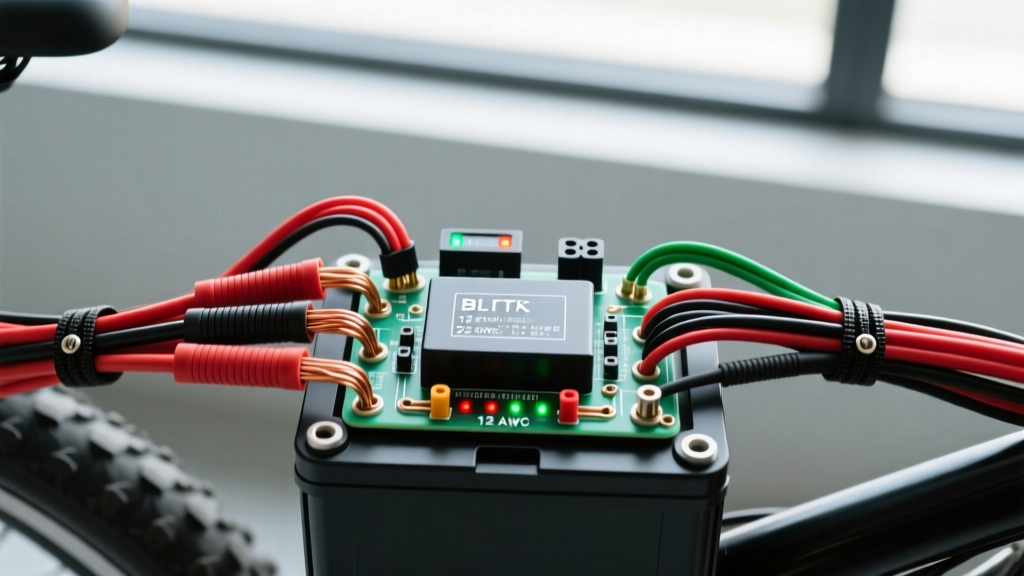
- Route the Red (Positive) 8 AWG wire from the BMS Discharge P+ pad to the controller's main positive terminal.
- Route the Black (Negative) 8 AWG wire from the BMS Discharge P- pad to the controller's main negative terminal.
- Crucial: Ensure your inline fuse (e.g., 50A ANL fuse) is placed on the positive wire, as close to the battery discharge terminal as physically possible.
Step 3: Ignition and Logic Wake
The thick red wire powers the motor, but the controller's brain needs a separate wake signal.
- Locate the thin Red Ignition/Lock wire on the controller's main harness.
- Connect this to a keyed ignition switch or a handlebar toggle switch that is fed by a stepped-down 12V or direct battery voltage (depending on controller specs) from the BMS.
- When this wire receives voltage, the controller's internal 5V regulator wakes up, powering the display and Hall sensors.
Step 4: Motor Phase and Hall Sensors
The motor connection consists of two distinct bundles:
- Phase Wires (Thick): Yellow, Green, and Blue. These carry the high-frequency, high-current AC square waves generated by the controller's MOSFET bridge. Match colors exactly to the motor. If the motor spins backward or stutters violently, swap any two phase wires.
- Hall Sensors (Thin): A 5-pin JST-SM connector containing Red (5V), Black (Ground), and Yellow/Green/Blue (Signal A, B, C). These tell the controller the exact rotor position. Never apply battery voltage to the Hall sensor pins; doing so will instantly fry the motor's internal Hall ICs, requiring a complete motor teardown to replace.
Integrating a Smart BMS (Daly / ANT / JBD)
Modern builds utilize Smart BMS units with active Bluetooth or CAN-bus communication. When reviewing your electric bike battery wiring diagram, the BMS sense wires are just as critical as the main discharge leads.
According to Battery University, cell imbalance in series-parallel configurations is the primary driver of premature pack death. A Smart BMS monitors individual cell group voltages via the multi-pin balance ribbon cable.
Common BMS Wiring Mistakes
- Plugging the balance harness in backward: This instantly shorts cell groups through the BMS microchips, destroying the BMS and potentially venting cells. Always verify pin 1 is 0V (B-) and the final pin is total pack voltage (e.g., 54.6V for 13S) using a multimeter before plugging it into the BMS.
- Ignoring the Temp Sensors: Smart BMS units include NTC thermistors. Zip-tie one sensor directly to the center cells of the pack, and the second to the MOSFET array on the BMS board. If omitted, the BMS cannot throttle discharge during thermal overload.
Troubleshooting Controller Error Codes
When your wiring is complete and you power on the system, the LCD display may throw error codes. Here is how to diagnose wiring-specific faults:
- Error 07 (Overvoltage): Your battery is wired to a controller rated for a lower voltage (e.g., plugging a 52V 14S battery into a strict 48V 13S controller). You must adjust the controller's LVC (Low Voltage Cutoff) and OVC (Over Voltage Cutoff) parameters via the programming cable.
- Error 08 (Hall Sensor Fault): The controller cannot read the motor position. Check the 5-pin JST connector for pushed-out pins or a broken 5V Red wire. Use a multimeter to verify exactly 4.8V to 5.0V between the Red and Black Hall pins at the controller side.
- Motor Stuttering / Loud Grinding: This is rarely a Hall sensor issue; it is almost always a loose or oxidized Phase wire connection. Disconnect the battery, inspect the 5.5mm bullet connectors for black soot (arcing), clean with contact cleaner, and re-crimp.
Final Verification Checklist
Before taking the bike on the road, perform a bench test. Elevate the rear wheel off the ground. Engage the ignition, apply the rear brake (to test the brake motor-cutoff switches), and gently roll the throttle. Monitor the battery voltage on a multimeter; under a light no-load spin, a 52V pack should not sag below 50V. If voltage collapses instantly, you have a high-resistance fault in your main discharge wiring or a failing BMS MOSFET. Proper execution of your electric bike battery wiring diagram ensures not only peak performance but the longevity and safety of your entire powertrain.