
Decoding the Standard Wiring Diagram for a Light and Switch
Understanding a wiring diagram for a light and switch is the foundational skill for any residential electrical project. Whether you are upgrading a vintage toggle to a modern smart switch or wiring a new addition, the diagram serves as your logical roadmap. However, a schematic on paper often looks vastly different from the physical reality inside a cramped junction box. In this 2026 reference guide, we bridge the gap between theoretical schematics and physical execution, focusing on the most common residential configuration: the single-pole switch controlling a single ceiling fixture.
Before touching a single wire, it is critical to understand that electrical diagrams prioritize logical flow over physical routing. A standard schematic shows power entering the switch, traveling to the light, and returning via the neutral. In modern physical installations, however, power often enters the light fixture box first, requiring a "switch loop" down to the wall switch. We will dissect both variations below.
Anatomy of the Single-Pole Schematic
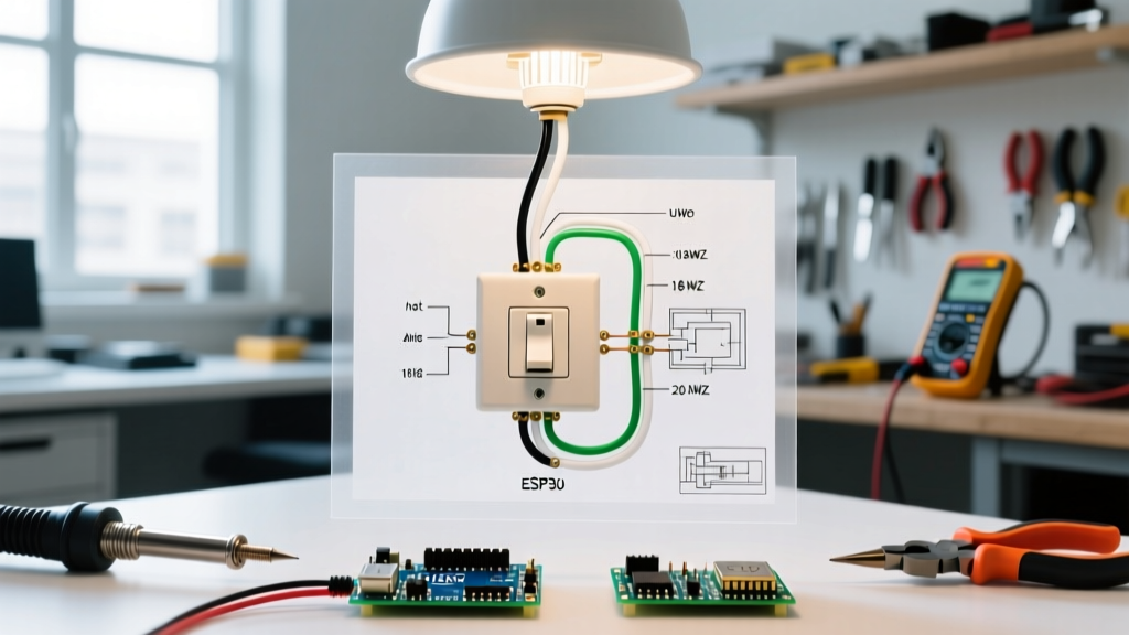
A standard single-pole wiring diagram consists of four primary conductors and three main nodes. Grasping the terminology is essential for troubleshooting and safe installation.
- Line (Hot): The ungrounded conductor bringing 120V AC from the circuit breaker panel. In standard NM-B (Romex) cable, this is the black wire.
- Load: The continuation of the hot conductor that carries power from the switch to the light fixture only when the switch is closed.
- Neutral (Grounded Conductor): The white wire that completes the circuit, carrying current back to the panel. Crucial note: A standard single-pole mechanical switch does not connect to the neutral wire.
- Ground (Equipment Grounding Conductor): The bare copper or green wire providing a safe fault path. It connects to the switch yoke, the metal box (if applicable), and the fixture canopy.
Wire Gauge and Breaker Sizing Matrix
Selecting the correct wire gauge is non-negotiable and strictly governed by the National Electrical Code (NEC). Using undersized wire on a high-amperage breaker is a leading cause of residential electrical fires. Always match your NM-B cable to the breaker rating.
| Circuit Breaker Rating | Minimum Wire Gauge (Copper) | NM-B Jacket Color | Max Continuous Load (80% Rule) | Common Application |
|---|---|---|---|---|
| 15 Ampere | 14 AWG | White | 12 Amps (1,440W) | Standard bedroom/hallway lighting |
| 20 Ampere | 12 AWG | Yellow | 16 Amps (1,920W) | Bathroom lighting (with exhaust fans), kitchen lighting |
Translating the Diagram to Physical Connections
Let us walk through the physical execution of the diagram, assuming a standard layout where power enters the switch box first via 14/2 NM-B cable, and a second 14/2 cable runs to the light fixture.
Step 1: Verification and Preparation
Shut off the breaker and verify the absence of voltage using a non-contact voltage tester (NCVT), such as the Klein Tools NCVT-3. Strip exactly 3/4-inch of insulation from the solid copper conductors using the 14 AWG hole on your wire strippers. Stripping too much leaves exposed copper outside the terminal; stripping too little causes insulation to bind under the screw, creating a high-resistance hot spot.
Step 2: The Switch Box Termination
Look closely at your single-pole switch (e.g., a Leviton 1451-2W). You will see two brass terminal screws and one green ground screw.
- Grounding: Connect the bare copper wires from both cables together with a green wire nut, and attach a 6-inch bare copper pigtail to the green ground screw on the switch.
- Neutral Bypass: Join the two white neutral wires together using a yellow wire nut (e.g., Ideal Wire-Nut #74B). Push them neatly to the back of the box. They do not land on the switch.
- Line and Load: Connect the black wire from the panel (Line) to one brass screw. Connect the black wire going to the fixture (Load) to the other brass screw. On a standard single-pole switch, Line and Load are interchangeable on the brass terminals.
Step 3: The Light Fixture Termination
At the ceiling canopy, the diagram simplifies. The incoming white wire connects to the fixture's silver/white lead. The incoming black (Load) wire connects to the fixture's black lead. The bare ground connects to the fixture's ground wire and the metal junction box grounding screw.
Modern Edge Cases: The Neutral Requirement and Smart Switches
If you are reading an older wiring diagram for a light and switch, you will likely encounter a "switch loop." In legacy wiring, power entered the ceiling fixture, and a single 14/2 cable was dropped to the switch. The white wire was used as a hot Line (which should be re-identified with black tape), and the black wire was the Load returning to the light. This meant no neutral wire existed in the switch box.
2026 NEC Compliance Alert: Under NEC Article 404.2(C), a neutral conductor is now required at nearly all switch locations. This code update was implemented to support modern smart switches, occupancy sensors, and Wi-Fi-enabled dimmers that require a small amount of standby current to operate their internal radios. If you are upgrading an older home, you must pull new 14/3 or 12/3 cable to the switch box to provide a dedicated neutral, even if the mechanical switch diagram does not require it.
Failure Mode: LED Flickering on Legacy Diagrams
A common issue in 2026 is installing a modern LED fixture on a legacy switch loop without a neutral. If you attempt to use a smart dimmer (like the Lutron Maestro MACL-153M) without a neutral, the dimmer attempts to trickle current through the LED bulb itself to complete its internal circuit. This results in the LED bulb flickering, ghosting, or flashing periodically. The only permanent fix is rewiring to include a neutral at the switch, aligning with modern diagrams.
3-Way vs. Single-Pole: Diagram Variations
When a single light must be controlled from two locations (e.g., top and bottom of a staircase), the single-pole diagram is discarded in favor of a 3-way switch schematic.
- Terminal Differences: A 3-way switch has one black "Common" screw and two brass "Traveler" screws, plus the ground.
- Wiring Complexity: The diagram requires a 14/3 NM-B cable (Black, Red, White, Bare) running between the two switches to carry the traveler currents.
- Line and Load: The Line connects to the Common screw of Switch 1. The Load connects to the Common screw of Switch 2. The travelers simply pass the hot state back and forth depending on the toggle positions.
Frequently Asked Questions
Can I wire the switch on the neutral wire instead of the hot wire?
Technically, the light will turn on and off. However, this is a severe violation of the OSHA electrical safety standards and the NEC. If the switch interrupts the neutral, the light fixture remains fully energized at 120V even when the switch is in the "OFF" position. Changing a bulb in this scenario poses a lethal shock hazard. The diagram must always show the switch interrupting the ungrounded (hot) conductor.
What is the torque specification for switch terminal screws?
While the NEC mandates specific torque values for circuit breaker terminals (NEC 110.14(D)), standard 15A wall switches do not typically have published inch-pound torque specs. However, industry best practice dictates tightening the terminal screw until the wire is firmly seated and cannot be pulled out with a gentle tug, usually about 1/4 to 1/2 turn past snug. Avoid over-torquing, which can strip the brass threads or shear the screw head.
Where can I find the official code requirements for switch wiring?
The definitive source for all residential wiring diagrams and code requirements in the United States is the National Fire Protection Association (NFPA). You can review the standards and adoption maps via the official NFPA National Electrical Code (NEC) portal. Always check your local municipal building department, as local jurisdictions may have specific amendments to the national code.
Final Safety and Execution Checklist
Before energizing the circuit, perform a physical audit of your work against the wiring diagram:
- Are all bare ground wires securely terminated to green screws and metal boxes?
- Is the neutral wire completely isolated from the switch terminals?
- Are there any loose "whiskers" of copper strand protruding from the wire nuts or terminal screws?
- Is the wire insulation pulled tight against the switch yoke, ensuring no bare copper is exposed outside the terminal?
By strictly adhering to the logical flow of the wiring diagram and respecting the physical limitations of your materials, you ensure a safe, code-compliant, and reliable lighting circuit that will perform flawlessly for decades.