
The GMT800 Platform: Aging Wiring and the Class II Data Bus
The 2000 Chevy Silverado, built on General Motors' legendary GMT800 platform, remains a staple on work sites and driveways in 2026. However, as these trucks cross the quarter-century mark, their electrical systems—specifically the infotainment and Body Control Module (BCM) networks—begin to exhibit unique failure modes. Whether you are diagnosing a dead factory unit, tracking down a parasitic battery drain, or integrating an aftermarket head unit, understanding the radio wiring diagram for a 2000 Chevy Silverado is your critical first step.
Unlike modern vehicles that rely on high-speed CAN bus networks, the 2000 Silverado utilizes the SAE J1850 VPW (Variable Pulse Width) Class II data bus. This single-wire communication protocol dictates everything from radio theft-deterrent lockouts to chime retention and OnStar integration. Misinterpreting this diagram doesn't just result in a silent stereo; it can trigger BCM sleep-mode failures that drain your battery overnight.
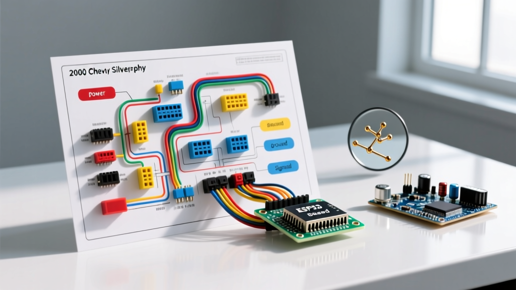
Decoding the Radio Wiring Diagram for a 2000 Chevy Silverado
The factory Delco head unit in the 2000 Silverado typically connects via a 24-pin harness, though only a fraction of the pins are populated. Below is the definitive pinout map for the primary power, ground, and data circuits. Note: Always verify with a digital multimeter (DMM), as 25 years of dealer repairs and aftermarket splices can alter factory wire colors.
| Pin / Circuit | Wire Color | Function | Troubleshooting Notes |
|---|---|---|---|
| Constant 12V (Battery) | Orange | Provides continuous power for memory and BCM wake-up. | If dead, check the 15A 'RADIO' fuse in the left dash fuse block. |
| Switched 12V (Ignition) | Yellow | Powers the unit on when the key is in RUN or ACC. | Often back-fed by a failing ignition switch if voltage drops below 11.5V. |
| Ground | Black | Main chassis ground. | Ties into the notorious G200 splice pack. High resistance here causes display flickering. |
| Class II Data Bus | Light Green | SAE J1850 VPW communication with the BCM. | Crucial for theft-lock reset and retaining door-chime audio. |
| Illumination | Brown/White | Dims the display when parking lights are engaged. | Often spliced incorrectly into aftermarket harnesses, blowing the 2A 'INST LPS' fuse. |
Step-by-Step Troubleshooting Using the Wiring Diagram
1. Diagnosing the Parasitic Draw (Orange Wire Circuit)
A common complaint in 2026 for GMT800 owners is a dead battery after the truck sits for 48 hours. The radio wiring diagram shows the Orange wire (Constant 12V) is always hot. When the BCM enters 'Sleep Mode' (which takes up to 20 minutes after the last door is closed), the radio should drop its current draw to under 10 milliamps.
- The Test: Connect a DMM in series with the negative battery terminal. Close all doors and wait 25 minutes. If the draw remains above 50mA, disconnect the radio harness.
- The Culprit: If the draw drops to normal, the internal capacitor of the factory radio has failed, or an aftermarket wiring adapter lacks proper diode isolation, keeping the Class II bus artificially awake.
2. The G200 Ground Splice Pack Failure
The black ground wire on your diagram doesn't just go to a simple ring terminal; it routes to the G200 ground splice pack, located under the driver's side kick panel carpet. This splice pack is infamous for corroding due to moisture ingress from the door seal.
Expert Warning: Never simply 'add another ground wire' to the radio chassis if you are experiencing static that revs with the engine. This masks the G200 corrosion and can cause back-feeding through the illumination circuit, eventually frying the BCM. Pull the carpet, locate the G200 pack, cut the corroded section, and solder the connections using marine-grade heat shrink.
3. Class II Data Line and 'LOCKED' Anti-Theft Modes
If you are swapping the radio and the display reads 'LOC' or 'LOCKED', the Class II data line (Light Green) is your focus. The factory Delco radio uses this line to verify the VIN with the BCM upon startup. If you are installing an aftermarket unit, you must use a data-bus interface module to simulate this handshake, otherwise, the vehicle's DIC (Driver Information Center) may throw a 'SERVICE THEFT SYSTEM' code.
Standard Delco vs. Bose Amplified Systems
Before cutting or splicing any wires based on the diagram, you must identify which audio architecture your 2000 Silverado uses. The wiring diagrams differ drastically between the base Delco system and the premium Bose package.
| Feature | Standard Delco System | Bose Amplified System |
|---|---|---|
| Amplification | Internal to head unit (High-Level) | External Amp (Low-Level RCA signals from head unit) |
| Amp Location | N/A | Under center console or passenger kick panel |
| Speaker Wires at Dash | 8 standard speaker wires (Tan, Gray, etc.) | No speaker wires; requires RCA bypass harness |
| Chime/OnStar Retention | Handled via standard Class II data | Requires specialized analog-to-digital chime module |
Essential 2026 Integration Hardware & Costs
If your troubleshooting reveals that the factory radio is dead and you are upgrading to a modern digital media receiver, do not rely on cheap, generic 'butt-splice' harnesses. The industry standard for vehicle integration dictates using vehicle-specific data interfaces to maintain safety features. According to NHTSA guidelines on vehicle modifications, improper electrical splices are a leading cause of aftermarket electrical fires.
- Standard Delco Harness (Metra 70-1858): Retailing around $18 - $25, this plug-and-play harness matches the factory Delco colors to standard EIA aftermarket colors. It includes the necessary resistor to trick the BCM into thinking the factory radio is still present for chime retention.
- Bose / OnStar Retention Module (Axxess GMOS-04): Priced between $65 - $85 in 2026, this module is non-negotiable for Bose-equipped Silverados. It steps up the low-level Bose signals, retains the factory amplifier turn-on lead (Pink wire on the Bose harness), and safely routes door chimes and OnStar alerts through the front left speaker.
- Dash Kit (Metra 99-2003): Costs approximately $15. Required to adapt the GMT800's curved double-DIN opening to a flat aftermarket receiver.
Expert FAQ: Silverado Radio Gremlins
Why does my aftermarket radio turn on when I open the door?
This happens when the Yellow (Switched 12V) wire is incorrectly wired to the Orange (Constant 12V) wire, or when an installer taps into the 'Retained Accessory Power' (RAP) circuit without a proper BCM interface. The 2000 Silverado's RAP system keeps the radio powered until the door opens. If your aftermarket harness isn't reading the Class II data bus to detect the 'Door Open' signal, it will stay on indefinitely until the BCM forces a hard shutdown, potentially corrupting the radio's memory.
My wiring diagram shows a Pink wire, but my truck doesn't have it. Why?
The Pink wire is the Amplifier Turn-On lead, exclusive to the Bose and Y91 (Luxury Audio) packages. If you are looking at a comprehensive GM service manual diagram, it includes all RPO (Regular Production Option) codes. If your truck lacks the external amplifier, that pin cavity on the 24-plug connector will simply be empty.
Can I just bypass the Class II data wire to save money on a harness?
Technically, you can wire an aftermarket radio using only the Orange (Constant), Yellow (Switched), and Black (Ground) wires, ignoring the data bus entirely. However, doing so will permanently disable your door chimes, turn-signal click sounds (if routed through the radio), and OnStar functionality. Given that a proper data-interface harness costs less than $30, bypassing the data line is a severe compromise to the vehicle's safety and usability profile.