
Understanding the Wiring Diagram for Dual Radio Mobile Setups
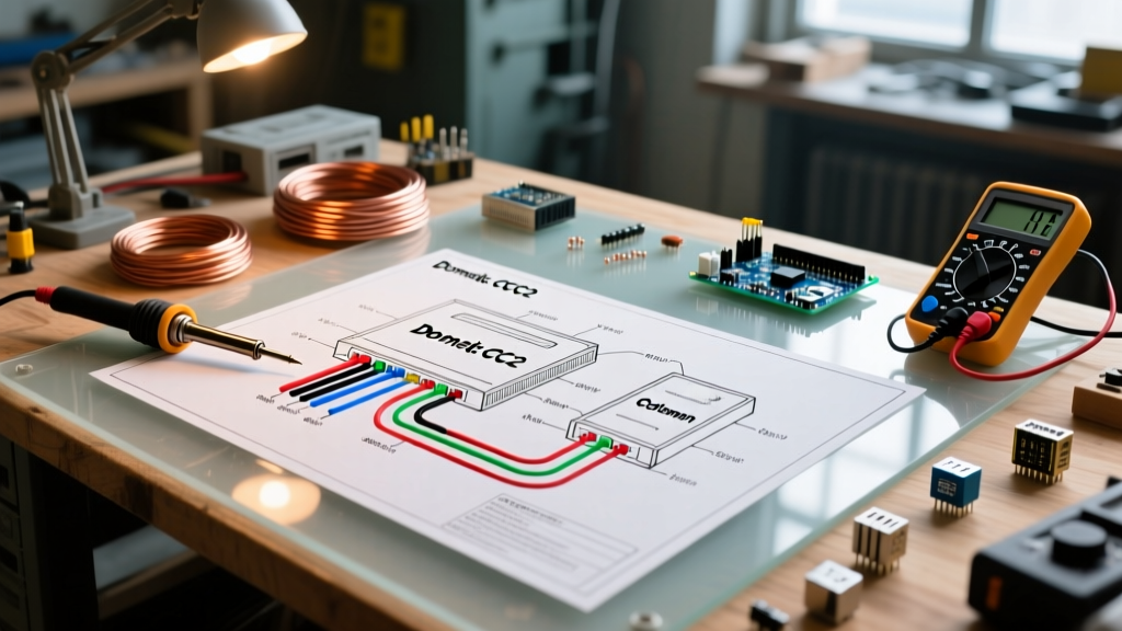
Installing a single mobile transceiver is a straightforward task, but engineering a reliable wiring diagram for dual radio configurations requires a meticulous approach to power distribution, voltage drop mitigation, and RF isolation. Whether you are pairing a high-power HF rig like the Icom IC-7100 with a VHF/UHF FM mobile unit like the Yaesu FT-8900R, or running dual VHF/UHF setups for emergency communications, the electrical architecture must handle simultaneous peak current draws without inducing alternator whine or triggering low-voltage shutdowns.
As of 2026, modern solid-state mobile transceivers are highly efficient, yet their peak transmit currents still demand robust copper pathways. A poorly designed dual radio wiring harness will result in severe voltage drop, causing the secondary radio to reboot or output distorted audio when the primary radio keys up. This guide provides a comprehensive, electrician-grade reference for designing, routing, and terminating a dual-radio mobile power and grounding system.
Core Electrical Requirements & Load Calculations
Before drawing your schematic, you must calculate the maximum simultaneous current draw. Most amateur radio operators mistakenly size their wiring based on the receive current or the continuous duty cycle. According to the ARRL Mobile and Portable Operations guidelines, wiring must be sized for the peak transmit current of both radios, plus a 25% safety margin to account for aging vehicle alternators and extreme temperature resistance.
Reference Load Table: Popular Dual Radio Configurations
| Radio Model | Band / Output | Peak TX Current | Recommended Inline Fuse |
|---|---|---|---|
| Yaesu FT-8900R | VHF 50W / UHF 35W | 11.0 Amps | 15A ATO Blade |
| Icom IC-2730A | VHF 50W / UHF 50W | 13.0 Amps | 20A ATO Blade |
| Kenwood TM-V71A | VHF 50W / UHF 50W | 12.5 Amps | 20A ATO Blade |
| Anytone AT-778UV | VHF 25W / UHF 20W | 6.5 Amps | 10A Mini-ATO |
Note: If running an HF mobile rig (e.g., Icom IC-705 or Yaesu FT-891), peak TX current can exceed 22 Amps, requiring an upgraded main trunk wire gauge.
Step-by-Step Power Distribution Layout
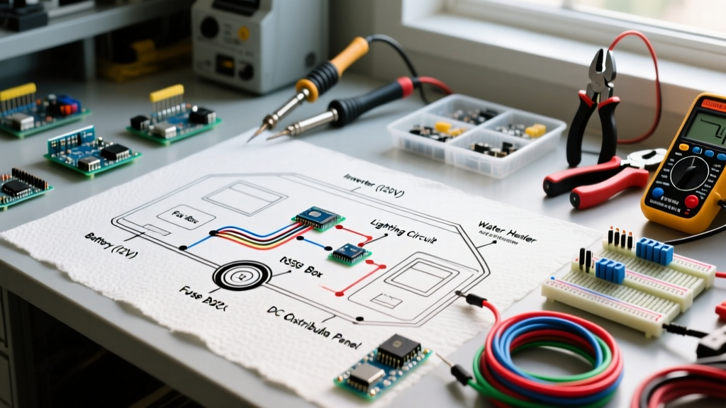
The most reliable wiring diagram for dual radio setups abandons direct-to-battery daisy-chaining in favor of a centralized, fused distribution block. This prevents multiple ring terminals from being stacked on a single battery post, which is a primary cause of arcing and thermal runaway.
1. The Main Trunk (Battery to Distribution Block)
Run a single, continuous positive lead from the vehicle battery to a centralized fuse block located in the cabin or trunk. For a combined peak load of 24 Amps (e.g., FT-8900R + IC-2730A) with a 12-foot cable run, 8 AWG stranded copper wire is mandatory. While 10 AWG is technically rated for 30 Amps, the 12-foot round-trip distance will introduce a voltage drop of nearly 0.6V at peak load. Mobile radios typically trigger low-voltage protection at 11.5V; starting from a resting vehicle voltage of 12.2V (engine off), a 0.6V drop will crash your radios during transmission.
Install a 40A ANL or Mega fuse within 6 inches of the battery positive terminal. This protects the main trunk wire in the event of a dead short before it reaches the cabin.
2. The Distribution Block & Branch Fusing
Mount a marine-grade distribution block, such as the Blue Sea Systems ST Blade 6-Circuit Fuse Block, under the dash or behind the kick panel. As detailed in the Blue Sea Systems Circuit Protection Overview, branch circuits must be fused individually based on the wire gauge and the specific device's maximum draw.
- Branch 1 (Radio A): 10 AWG wire protected by a 20A ATO fuse.
- Branch 2 (Radio B): 10 AWG wire protected by a 20A ATO fuse.
- Branch 3 (Accessories): 12 AWG wire protected by a 10A fuse for cooling fans or SWR meters.
3. Termination & Crimping Standards
Do not use solder for automotive DC power connections; solder joints become brittle under engine bay vibration and can crack, leading to high-resistance arcing. Use adhesive-lined heat shrink ring terminals and a dedicated ratcheting crimping tool (e.g., Knipex 13 72 8 or Titan 11240). The adhesive lining seals out moisture, preventing copper oxidation over time.
Grounding Topology: Eliminating Alternator Whine
The negative return path is where 90% of dual radio audio issues originate. If you ground Radio A to a seatbelt bolt and Radio B to a dashboard bracket, you create a ground loop. The alternator's AC ripple current will flow through the audio shields of your radios, resulting in a high-pitched whine that pitch-shifts with engine RPM.
The Single-Point Star Ground Method
Expert Rule of Thumb: Never rely on factory vehicle chassis grounds for high-current RF equipment. Factory grounding points are designed for low-current sensors and lighting, not the transient 20A+ return currents of a dual radio transmit event.
- Install a dedicated copper grounding busbar (e.g., Blue Sea 150A BusBar) in the cabin, securely bolted to bare, unpainted chassis metal using a star washer to bite through the factory paint and primer.
- Run a 4 AWG bonding cable from this busbar directly to the vehicle battery's negative terminal.
- Route the negative leads from both radios directly to this single busbar. This ensures both radios share the exact same reference potential, completely eliminating differential ground loops.
Antenna Isolation & Coax Routing
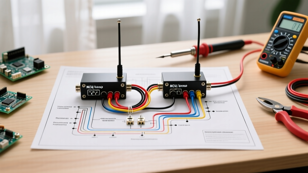
A wiring diagram for dual radio systems is incomplete without addressing RF routing. Transmitting 50 watts on VHF while the secondary UHF radio is receiving can instantly destroy the front-end mixer diodes of the receiving radio if the antennas are improperly placed.
- Physical Separation: If using two separate NMO mounts, ensure a minimum physical separation of 36 inches (3 feet) between the antenna whips. This provides roughly 20dB of passive isolation.
- Coax Routing: Keep RG-58 or LMR-240 coaxial cables physically separated from your DC power wiring by at least 4 inches. If they must cross, cross them at a strict 90-degree angle to minimize inductive coupling.
- Ferrite Chokes: Snap Fair-Rite 2643625002 ferrite beads onto the DC power cords of both radios, placed within 2 inches of the radio's rear chassis connector. This prevents the power cables from acting as accidental RF antennas, which can cause the radio's internal microprocessor to lock up during high-SWR transmit events.
Common Failure Modes & Troubleshooting Matrix
Even with a perfect schematic, environmental factors can degrade performance. Use this diagnostic matrix to troubleshoot post-installation anomalies.
| Symptom | Probable Cause | Diagnostic Action |
|---|---|---|
| Radio reboots when transmitting at 50W | Excessive voltage drop on main trunk | Measure voltage at radio chassis during TX. If below 11.8V, upgrade main trunk to 6 AWG. |
| High-pitched whine in transmitted audio | Ground loop / Alternator ripple | Verify both radios share a single copper busbar. Check for corroded chassis bite-points. |
| Secondary radio locks up during TX | RF ingress on DC power lines | Install mix-31 or mix-43 ferrite chokes on DC leads. Check coax shield continuity. |
| Blown branch fuses upon key-up | Inrush current spike / Failing PA final | Inspect radio internal power MOSFETs. Ensure ATO fuses are time-delay if specified by OEM. |
Compliance and Safety Standards
When routing wiring through the vehicle firewall, always use a rubber grommet and secure the cable with a P-clamp to prevent the metal firewall from slicing through the insulation over time. Adhering to the routing and overcurrent protection standards outlined in the NFPA 70 National Electrical Code (specifically Article 240 regarding overcurrent protection placement) ensures your mobile installation remains safe, insurable, and reliable for years of field operation.
Frequently Asked Questions
Can I use the vehicle's cigarette lighter socket for a dual radio setup?
No. Factory 12V accessory sockets are typically wired with 16 AWG wire and a 10A or 15A fuse. A single 50W mobile radio can draw 11-13 Amps at peak. Connecting two radios will instantly blow the factory fuse, melt the socket wiring, or cause a dashboard fire.
Do I need a relay to switch power to both radios?
While not strictly required for the power delivery, wiring the "ACC" (accessory) trigger wires of both radios to a single 30A automotive relay controlled by the ignition switch is highly recommended. This prevents you from accidentally leaving the radios on when you exit the vehicle, which will drain the vehicle's starter battery within 4 to 6 hours.
What is the best quick-disconnect for dual radio power?
Anderson Powerpole connectors (specifically the 45A APP-SB50 series) are the industry standard for amateur radio DC power. They allow you to instantly disconnect and remove the radios for security without cutting wires or unscrewing terminals.