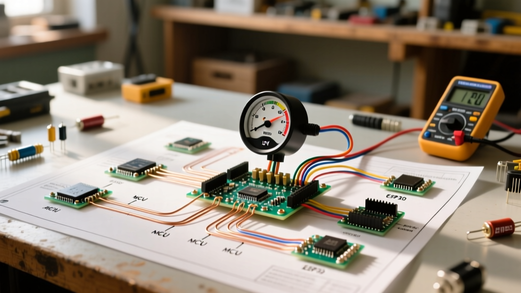

Treating Your Tachometer as a Precision 12V Appliance
When upgrading an instrument cluster or performing an engine swap, enthusiasts often treat gauges as simple plug-and-play accessories. In reality, an aftermarket tachometer is a highly sensitive frequency-to-voltage appliance. Whether you are installing a classic air-core model like the AutoMeter Ultra-Lite 5397 (typically retailing between $85 and $95 in 2026) or a modern stepper-motor variant pushing $180, understanding the underlying electrical architecture is critical. A flawed installation won't just give you inaccurate readings; it can introduce alternator whine into your audio system or completely fry the gauge's internal logic board.
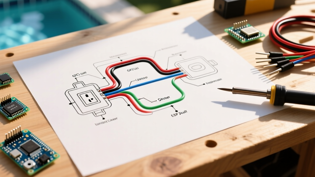
This comprehensive wiring diagram for auto gauge tachometer setups applies to standard 4-wire aftermarket electric tachometers. We will break down the exact pinouts, wire gauge requirements, ignition signal compatibility, and the crucial calibration steps required to get your needle tracking perfectly from idle to redline.
Ignition System Compatibility & Pulse Rates
Before cutting a single wire, you must identify your ignition system's pulse rate. The tachometer calculates RPM by counting the voltage pulses sent to the coil (or ECU) per revolution. Sending the wrong pulse rate to the gauge will result in the needle reading exactly half, double, or entirely erratically compared to actual engine speed.
| Ignition Type | Typical Pulse Rate | Signal Source | Notes / Adapters Required |
|---|---|---|---|
| Points / Standard Coil | 1 Pulse / Rev | Coil Negative Terminal | Direct connection. Ensure dwell is set correctly. |
| HEI / Distributorless (DIS) | 2 Pulses / Rev | Coil Negative or Tach Output | Most common for 80s-90s V8s. Direct connection usually works. |
| LS / Modern EFI (Coil-Near-Plug) | Variable / 2-4 Pulses | ECU Dedicated Tach Pin | Often requires a tach adapter (e.g., Holley 558-300) to convert 5V logic to 12V square wave. |
| MSD / Aftermarket CDI | 1 Pulse / Rev (12V Square) | CDI Box Tach Output (White Wire) | Never connect directly to the coil negative on a CDI system; the high voltage will destroy the gauge. |
The Core Wiring Diagram for Auto Gauge Tachometer
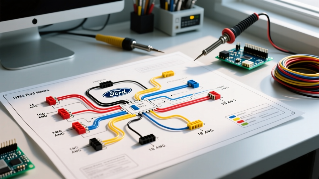
Standard electric tachometers utilize a 4-wire harness. Below is the exact pinout and wire gauge specification for a robust, noise-free installation. According to aftermarket wiring standards outlined by SEMA, using the correct wire gauge and proper termination is mandatory to prevent voltage drop and subsequent gauge flutter.
Wire Color Code and Pinout Breakdown
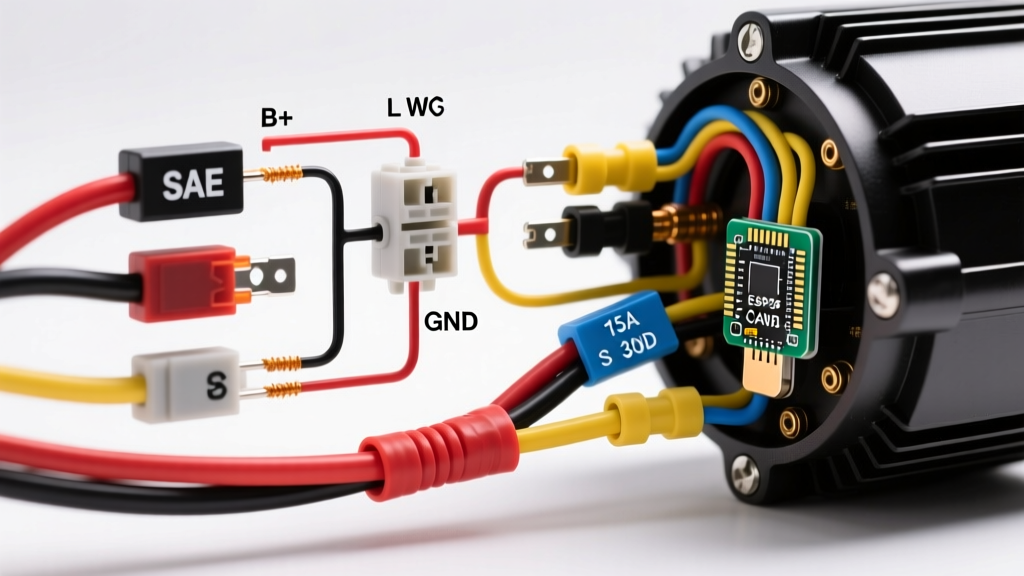
- Red Wire (Switched +12V Power): Use 16 AWG primary wire. Connect to an ignition-switched 12V source. Pro-Tip: Do not tap into the ignition coil's positive terminal for power, as voltage spikes during cranking can damage the gauge. Use a dedicated fuse block tap with a 3A inline fuse.
- Black Wire (Ground): Use 16 AWG. This is the most common point of failure. The ground must terminate at a clean, bare metal point on the engine block or main chassis ground bus. Never ground a tachometer to the steering column or a painted dashboard bracket.
- Green Wire (Tachometer Signal): Use 18 AWG. Connect to the coil negative, ECU tach output, or CDI box tach wire. This wire carries a low-current square wave signal and is highly susceptible to Electromagnetic Interference (EMI).
- White Wire (Lighting): Use 18 AWG. Connect to your dashboard illumination circuit (headlight switch) or a dedicated 12V PWM dimmer module for adjustable LED brightness.
Step-by-Step Installation Protocol
Follow this appliance-grade installation sequence to ensure longevity and accuracy.
Step 1: Power and Ground Termination
Route the 16 AWG red and black wires through the firewall using a sealed grommet. Terminate the red wire at a switched fuse in the interior fuse panel using an add-a-circuit tap. For the black wire, sand away any paint or powder coating at your chosen chassis ground point, apply a dielectric grease after tightening the ring terminal, and secure it with a stainless steel bolt.
Step 2: Routing the Signal Wire (EMI Shielding)
The green signal wire is the lifeline of your wiring diagram for auto gauge tachometer accuracy. High-tension spark plug wires and alternator stators emit massive electromagnetic fields. Route the green wire at least 4 inches away from any spark plug wires, distributor caps, or high-amperage alternator cables. If you must cross a high-voltage wire, do so at a strict 90-degree angle to minimize inductive coupling.
Step 3: Lighting Circuit Integration
Wire the white lead to your dash dimmer switch. If your vehicle uses a modern CAN-bus system that multiplexes lighting data rather than providing a raw 12V dimmer wire, you will need to install a CAN-bus to analog 12V lighting adapter to prevent dashboard error codes.
Calibration: Setting the Pulse Rate and Cylinders
Once physically wired, an air-core tachometer (like the AutoMeter Sport Comp or Ultra-Lite series) must be calibrated to your engine's specific pulse rate. While many modern units feature dip-switches on the back, the most accurate method utilizes the built-in calibration button and a known RPM signal.
Expert Calibration Trick: If you do not have a signal generator, use a timing light. Connect a timing light to cylinder #1. Start the engine and hold it at a steady RPM. Adjust the tachometer's calibration potentiometer or digital setting until the displayed RPM matches the RPM reading on an OBD2 scanner or a known-good diagnostic tachometer.
For push-button calibration models, the standard procedure is:
- Turn the ignition to the 'ON' position (engine off).
- Press and hold the calibration button on the back of the gauge for 5 seconds until the needle sweeps to half-scale.
- Start the engine and rev it to exactly 4,000 RPM (verify via a scan tool or timing light tach).
- Press the calibration button once more. The gauge will save the frequency-to-voltage ratio to its internal EEPROM.
Advanced Troubleshooting & Edge Cases
Even with a perfect wiring diagram for auto gauge tachometer setups, real-world variables can introduce faults. Here is how to diagnose the most common failure modes using a digital multimeter (DMM).
Needle Pegs at Maximum RPM and Stays There
Diagnosis: This almost always indicates a lost ground or a short to +12V on the green signal wire.
Fix: Set your DMM to DC Voltage. Probe the black ground wire at the gauge end while the ignition is on. If you read anything above 0.05V, your ground circuit has high resistance. Clean the ground terminal or run a dedicated 16 AWG ground wire directly to the battery negative.
Needle Bounces Erratically or Reads Double RPM
Diagnosis: Inductive noise (alternator whine) or incorrect pulse rate settings.
Fix: First, verify your pulse setting matches the ignition table above. If the setting is correct, switch your DMM to AC Voltage and probe the green signal wire while the engine is running. If you see high AC ripple voltage (above 2V AC), your signal wire is picking up EMI. Reroute the wire away from the alternator, or replace the green wire with a shielded coaxial audio cable, grounding the shield at the ECU end only.
Gauge is Completely Dead (No Sweep, No Light)
Diagnosis: Blown internal fuse or no switched power.
Fix: Check the 3A inline fuse on the red wire. If intact, use a test light on the red wire at the gauge connector with the key in the 'RUN' position. If the test light doesn't illuminate, trace the power circuit back to the fuse panel.
Frequently Asked Questions
Can I use a tachometer designed for a 4-cylinder on a V8 engine?
Yes, but only if the gauge is adjustable. Most modern aftermarket tachometers allow you to change the cylinder/pulse setting via dip switches or digital calibration. However, if you are using a vintage, fixed-ratio tachometer, it will read incorrectly and cannot be used without an external signal converter.
Do I need a tach adapter for my LS-swapped project?
In most cases, yes. Factory LS engine control modules output a 5V square wave tach signal, while standard analog aftermarket tachometers expect a 12V square wave. As detailed in Holley Performance technical documentation, using a dedicated tach adapter (like the Holley 558-300 or MSD 8918) ensures the 5V logic signal is safely stepped up to a 12V square wave without damaging the ECU.
Why does my tachometer needle drop to zero when I hit the brakes?
This is a classic symptom of voltage drop on the power or ground circuit. When you hit the brakes, the brake light circuit draws significant amperage. If your tachometer shares a ground bus or power feed with the brake lights, the sudden voltage drop starves the gauge. Run a dedicated, isolated power and ground for your instrument cluster.
Final Thoughts on 12V Instrument Wiring
Successfully executing a wiring diagram for auto gauge tachometer installation requires more than just matching wire colors. It demands an understanding of signal integrity, proper grounding topology, and EMI mitigation. By treating your gauge as a precision appliance, utilizing 16 AWG for power/ground, 18 AWG for signals, and strictly adhering to isolation routing, you will achieve a buttery-smooth needle sweep that accurately reflects your engine's performance for years to come. For further reading on automotive electrical standards and grounding practices, refer to the technical resources available via AutoMeter's official support channels.