
The Voltage Drop Problem in Classic Vehicles
If you own a classic truck—such as a 1967-1991 Chevrolet C/K or a 1980-1996 Ford F-Series—you have likely experienced dim headlights or a melted dash-mounted headlight switch. In these older vehicle-specific architectures, the factory wiring routes the full electrical load of the headlights (often 10 to 15 amps) directly through the dashboard switch, the firewall bulkhead connector, and decades-old copper wiring. This long, high-resistance path results in severe voltage drop, meaning your bulbs might only receive 10.5 volts instead of the optimal 13.8 to 14.4 volts provided by the alternator.
The definitive solution is installing a headlight relay harness. By utilizing a wiring diagram for headlight relay configurations, you bypass the factory switch entirely for the heavy current load. The dash switch merely acts as a low-amp trigger signal, while the relay handles the heavy lifting directly from the battery or alternator. This guide breaks down the exact schematics, wire gauges, and installation procedures required to upgrade your classic vehicle's lighting system safely and effectively.
Decoding the Wiring Diagram for Headlight Relay Systems
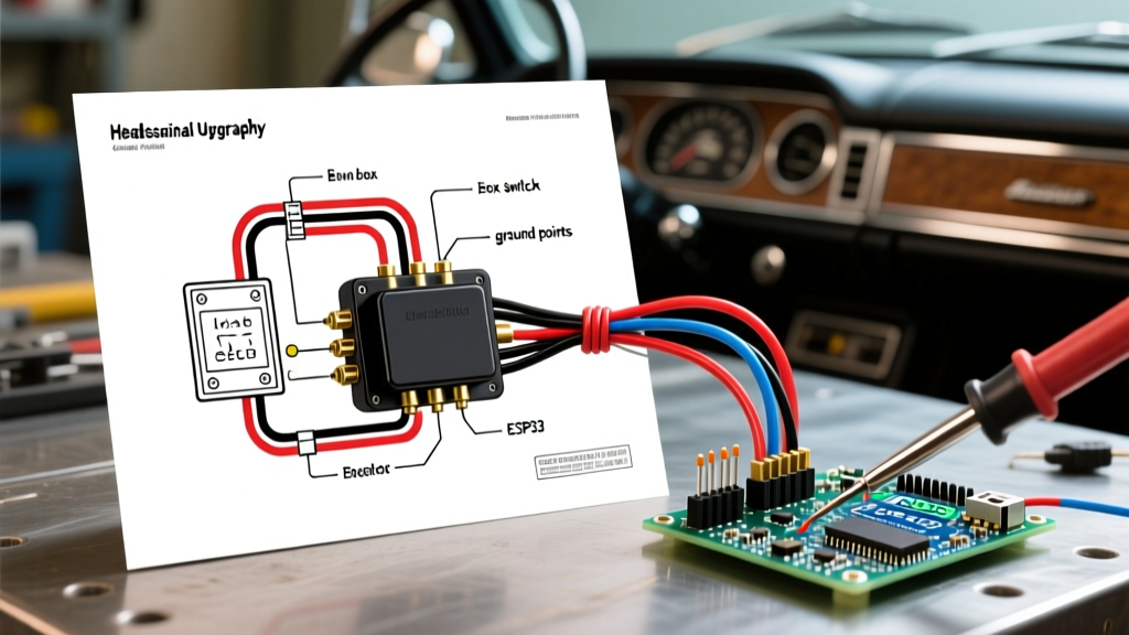
Before cutting a single wire, you must understand the anatomy of the standard automotive 12V relay. Most headlight upgrade kits utilize a standard 4-pin SPST (Single Pole, Single Throw) Bosch-style relay. Here is how the pins map out on the schematic:
Standard 4-Pin Relay Pinout Breakdown
- Pin 30 (Common / Power In): Connects directly to the positive battery terminal or a high-amperage distribution block. This is your heavy current source.
- Pin 87 (Normally Open / Power Out): Connects to the headlight positive wires. When the relay is energized, power flows from Pin 30 to Pin 87.
- Pin 86 (Coil Power / Trigger In): Connects to the factory headlight switch output wire. This provides the low-amp 12V signal to activate the relay's internal electromagnet.
- Pin 85 (Coil Ground): Connects to a clean, bare-metal chassis ground. This completes the low-amp trigger circuit.
Expert Note: Avoid 5-pin SPDT relays (which include a Pin 87a) for headlight applications unless you are building a complex daytime running light (DRL) circuit. If a 5-pin relay is used, Pin 87a must be capped and insulated; otherwise, backfeed voltage can energize other circuits when the headlights are turned off.
Wire Gauge and Component Selection Matrix
Selecting the correct wire gauge is critical. Using wire that is too thin will recreate the exact voltage drop issue you are trying to solve. The table below outlines the exact specifications for a dual-relay system (one relay for low beams, one for high beams) based on standard automotive wire ampacity charts.
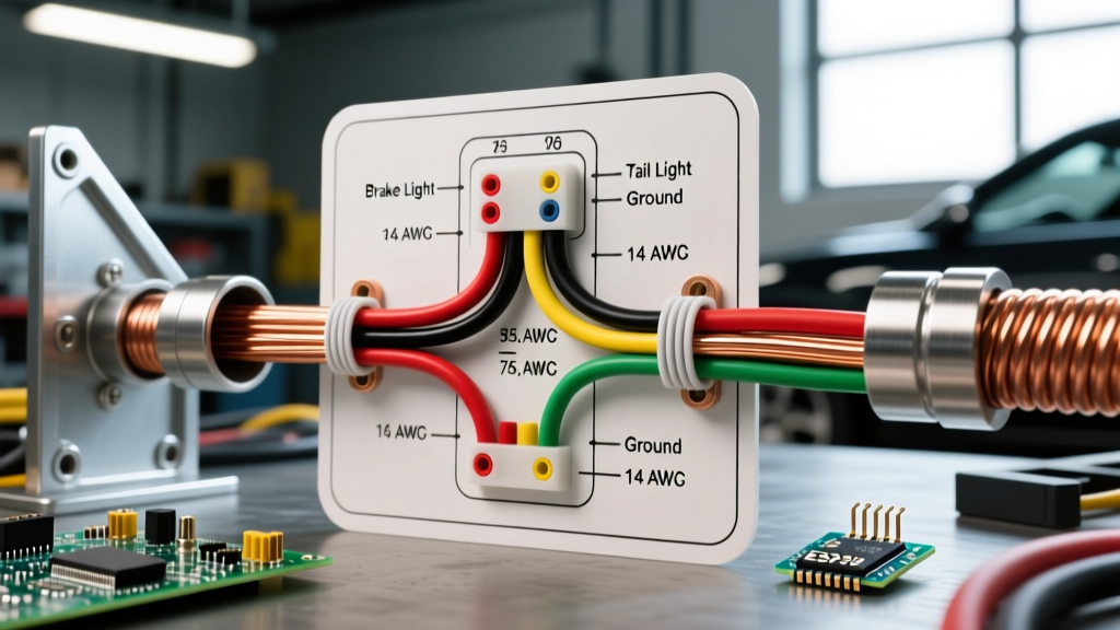
| Circuit Segment | Recommended Wire Gauge | Expected Amperage | Terminal Type |
|---|---|---|---|
| Battery to Relay (Pin 30) | 10 AWG Primary Wire | 15A - 25A | Ring Terminal (5/16") |
| Relay to Headlights (Pin 87) | 12 AWG Primary Wire | 10A - 15A | Spade / Weatherpack |
| Factory Switch Trigger (Pin 86) | 16 AWG Primary Wire | < 1A | T-Tap or Solder Sleeve |
| Relay to Chassis Ground (Pin 85) | 14 AWG Primary Wire | < 1A | Ring Terminal (1/4") |
Step-by-Step Installation & Wire Routing
For this installation, we assume you are upgrading to higher-wattage H4 (9003) halogen bulbs or high-output LED replacements, which demand a robust power supply. You will need two relays, a 30A maxi-fuse holder, and roughly 25 feet of automotive-grade cross-linked polyethylene (XLPE) wire.
- Disconnect the Battery: Always remove the negative battery terminal first to prevent dead shorts while routing the Pin 30 power wire.
- Mount the Relays: Position the relays on the inner fender well or radiator support, as close to the battery and headlights as possible. Use self-tapping stainless steel screws with fender washers. Ensure the relay pins face downward to prevent water intrusion into the spade connectors.
- Run the Main Power (Pin 30): Strip the 10 AWG wire and crimp a ring terminal using a ratcheting crimper (such as the Titan 11904). Install a 30A maxi-fuse within 6 inches of the battery positive post. Route the wire through split-loom tubing to protect it from engine bay heat and abrasion.
- Tap the Trigger Wire (Pin 86): Locate the factory low-beam and high-beam trigger wires near the factory headlight pigtail. Instead of using cheap T-taps (which can cut through corroded vintage copper), strip back 1/2 inch of the factory wire, solder the 16 AWG trigger wire, and seal it with 3M FP-301 heat shrink tubing.
- Establish the Ground (Pin 85): Find a clean, unpainted metal surface on the chassis. Sand away paint and primer, attach the 14 AWG ground wire with a star washer to ensure a gas-tight connection, and coat the area with dielectric grease to prevent future oxidation.
- Route to Headlights (Pin 87): Run the 12 AWG output wires to the headlight buckets. Connect them to the positive pins of your new H4 ceramic headlight pigtails. Ensure the factory headlight harness is disconnected and taped up, as it will no longer carry the load.
Real-World Failure Modes and Edge Cases
Even with a perfect schematic, physical installation errors can cause system failure. Based on diagnostic data from classic truck restorations, here are the most common edge cases:
1. The "Ghost Voltage" Backfeed
If you leave the factory headlight harness plugged into the back of the headlight bulb while also powering it via the new relay, you create a parallel circuit. When the lights are turned off, alternator ripple voltage can backfeed through the factory harness, causing LEDs to flicker or glow faintly. Solution: Always isolate the factory harness or use a dedicated relay harness that completely unplugs from the factory circuit.
2. Voltage Drop Across the Relay Contacts
Cheap, mass-produced relays (often found in $10 kits online) use low-grade copper alloys for the internal switching contacts. Under a 15A load, these contacts can heat up and introduce a 0.5V to 1.0V drop. Solution: Purchase name-brand relays like the Bosch 0 332 014 150 or EPAuto EP085. Test the voltage drop across Pins 30 and 87 with a digital multimeter while the headlights are on; it should read less than 0.1V.
3. Inadequate Grounding Causing Melted Pigtails
Many DIYers use the factory, undersized ground wire on the headlight harness to ground the new relay circuit. The factory ground was designed for 45W sealed beams, not modern 60/55W H4 bulbs. This bottleneck causes the ground wire to overheat and melt the plastic headlight pigtail. Solution: Run a dedicated 12 AWG ground wire directly from the negative terminal of the headlight pigtail to a verified chassis ground.
Frequently Asked Questions
Do I need a relay for LED headlight upgrades?
Generally, LEDs draw significantly less current (often 2 to 3 amps per bulb) compared to halogens. However, installing a relay is still highly recommended for classic vehicles. The factory wiring and bulkhead connectors are often heavily corroded after 40 years. A relay ensures your LEDs receive a steady, clean 14V signal, which prevents the internal LED drivers from overheating and failing prematurely due to voltage fluctuations.
Can I use a single relay for both high and low beams?
No. Standard H4 bulbs have two separate positive filaments (one for low, one for high) and share a common ground. You must use two separate relays: one triggered by the factory low-beam wire, and one triggered by the factory high-beam wire. Attempting to wire both through a single relay will result in both beams turning on simultaneously or backfeeding into the dash indicator.
What is the cost difference between DIY and pre-made kits?
Building your own harness using high-grade XLPE wire, Bosch relays, and a ratcheting crimper will cost roughly $35 to $45 in materials. Pre-made kits, such as the Painless Performance 30812 Headlight Harness, cost between $65 and $85. While pre-made kits save time, they often use standard PVC wire that becomes brittle in high-heat engine bays after a few years. For a show-quality, long-lasting installation, the DIY route with premium materials is superior.
For further reading on classic GM electrical schematics and bulkhead connector pinouts, the archives at Mad Electrical remain the industry gold standard for vehicle-specific wiring diagrams. By properly executing your wiring diagram for headlight relay systems, you not only achieve vastly superior nighttime visibility but also protect your classic truck's fragile, irreplaceable factory dash switch from catastrophic thermal failure.