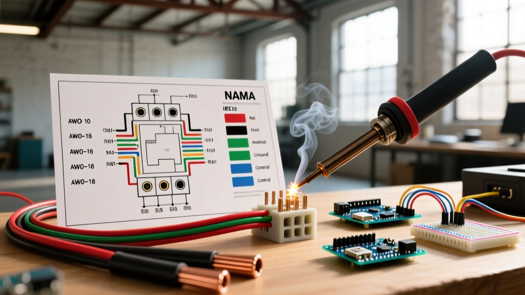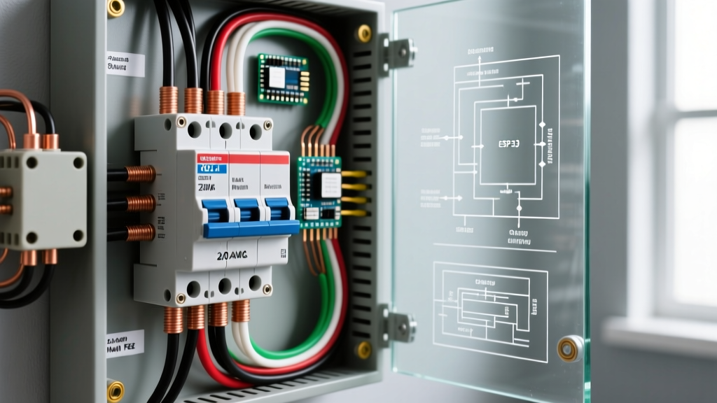

The Anatomy of a 200-Amp Main Breaker Panel
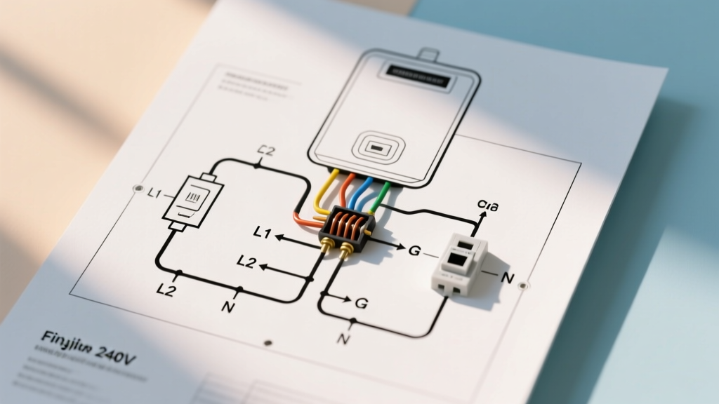
When undertaking the complex task of wiring an electrical panel, understanding the physical and electrical layout of a 200-amp main breaker load center is your first critical step. A 200-amp service is the modern standard for residential homes, capable of supporting high-draw appliances like electric vehicle (EV) chargers, tankless water heaters, and dual HVAC systems. While many online searches focus on the basics of wiring a electrical panel, true expertise requires a deep dive into bus bar configurations, neutral-ground bonding, and precise termination protocols.
CRITICAL SAFETY WARNING: Working inside a main service panel exposes you to the utility service drop lugs. These lugs remain energized at 240V even when the main breaker is switched OFF. Always verify the utility has disconnected power at the meter, or use an appropriately rated CAT IV multimeter and arc-flash PPE before touching service conductors. Consult the OSHA Electrical Safety Guidelines before proceeding.
Core Components and Layout Reference
A standard 200-amp residential panel, such as the widely installed Square D HOM200M125CP (Homeline series) or the Siemens P0816B1125CU, shares a universal architectural diagram:
- Service Lugs: The mechanical termination points for the incoming utility feeder cables (typically located at the top of the panel).
- Main Breaker: A 2-pole, 200A thermal-magnetic trip mechanism that protects the bus bars and serves as the primary service disconnect (required by NEC Article 230.70).
- Hot Bus Bars: Two parallel aluminum or copper-plated aluminum stabs that distribute 120V each, 180 degrees out of phase, yielding 240V across both.
- Neutral Bar (Grounded Conductor):strong> A dedicated bus bar with set-screws for terminating white/gray neutral wires and the main service neutral.
- Equipment Grounding Bar (EGC):strong> A separate bar bonded to the panel enclosure for bare copper or green ground wires.
Wire Sizing and Feeder Specifications
Selecting the correct wire gauge for the service entrance conductors is governed by NFPA 70 (National Electrical Code) Article 310.12. For a standard single-phase, 3-wire, 200-amp residential service, the NEC provides specific minimum sizing allowances that differ from standard branch circuit calculations.
| Conductor Material | Insulation Type | Minimum AWG/kcmil | Ampacity (75°C Column) | Approx. Cost per Foot (2026) |
|---|---|---|---|---|
| Aluminum (AL) | XHHW-2 / THWN-2 | 4/0 AWG | 180A (Allowed for 200A service per 310.12(B)) | $8.50 - $11.00 |
| Copper (CU) | THHN / THWN-2 | 2/0 AWG | 175A (Allowed for 200A service per 310.12(B)) | $22.00 - $28.00 |
| Aluminum SER Cable | XHHW-2 (4-conductor) | 4/0-4/0-4/0-2/0 | 180A (Phase) / 90A (Neutral) | $14.00 - $18.00 |
Expert Insight: While copper offers superior conductivity and resistance to galvanic corrosion, 4/0 AWG Aluminum SER (Service Entrance Rated) cable is the industry standard for 2026 residential builds due to its 60% cost savings and lighter weight, which makes pulling through 2-inch PVC service masts significantly easier.
Torque Specifications: The Most Overlooked NEC Requirement
Since the 2017 NEC cycle, and strictly enforced in 2026 inspections, Article 110.14(D) mandates that all electrical connections must be torqued to the manufacturer's specified values using a calibrated torque tool. Hand-tightening lugs based on 'feel' is a primary cause of thermal failure, arcing, and panel fires.
Manufacturer Torque Data (Square D & Siemens)
- Main Service Lugs (4/0 AL): 250 in-lbs (approx. 21 ft-lbs). Requires a heavy-duty torque wrench or large click-type torque screwdriver.
- Main Neutral Lug: 250 in-lbs.
- Neutral/Ground Bus Bar Set Screws: 45 in-lbs. Over-torquing these small screws will strip the aluminum threads, ruining the entire bus bar.
- Branch Circuit Breakers (15A - 50A): 35 in-lbs. Use a calibrated torque screwdriver like the Klein Tools 61082 or CDI 401SMV-2-A.
Step-by-Step Termination and Routing Sequence
Proper sequencing prevents crowding, ensures adequate bending radius, and keeps the panel organized for future troubleshooting. Follow this exact order when wiring an electrical panel:
- Prepare the SER Cable: Strip the outer jacket back exactly 48 inches from the entry knockout. This provides enough slack to route the conductors along the exterior gutter without stressing the insulation. Do not nick the inner conductor insulation.
- Apply Anti-Oxidant Paste: If using aluminum conductors, apply a UL-listed anti-oxidant compound (such as Noalox or Penetrox E) to the stripped aluminum wire before inserting it into the lug. This prevents aluminum oxide buildup, which is highly resistive and causes heat.
- Land the Grounding Conductor First: Terminate the bare equipment grounding conductor to the panel enclosure ground bar. Torque to 45 in-lbs.
- Land the Neutral Conductor: Route the white/gray neutral to the main neutral bar. In a main service panel, the neutral bar is bonded to the enclosure via the main bonding jumper (a green screw or metal strap provided with the panel). Torque to 250 in-lbs.
- Land the Hot Conductors (L1 and L2): Route the black and red (or taped white) phase conductors to the main breaker lugs. Ensure the bending radius complies with NEC Table 300.34 to prevent insulation stress. Torque to 250 in-lbs.
- Install the Main Bonding Jumper: If not pre-installed, drive the green main bonding screw through the neutral bar into the panel enclosure back. This is the only point in the entire electrical system where the neutral and ground are bonded together (NEC 250.24(A)(5)).
Common Failure Modes and Edge Cases
Even experienced electricians can make critical errors when wiring an electrical panel. Avoid these specific failure modes:
1. Double-Tapping on Non-Rated Lugs
Placing two conductors under a single lug set-screw is a direct NEC violation (Article 110.14(A)) unless the lug is explicitly listed and marked for two wires. Square D HOM and QO panels allow double-tapping only on specific circuit breakers (usually 15A-30A) where the pressure plate has a center ridge. The neutral and ground bars generally do not allow double-tapping; every neutral must have its own dedicated hole and screw.
2. Neutral-to-Ground Bonding in Subpanels
A frequent and dangerous error is leaving the main bonding screw installed in a subpanel. In any panel downstream of the main service disconnect, the neutral and ground must remain isolated. If bonded in a subpanel, normal neutral return current will travel along the bare equipment grounding wires, creating a shock hazard and potential electromagnetic interference (EMI) on sensitive electronics.
3. Overcrowding and Wire Fill Limits
NEC Article 312.8 dictates that the wiring space at any cross-section must not exceed 40% fill capacity. Cramming 12/2 and 10/2 NM-B cables into a shallow panel creates heat traps and makes future breaker swaps impossible. If a panel is full, upgrade to a deeper enclosure (e.g., moving from a 4-inch deep panel to a 5.75-inch deep 'extended' gutter panel).
Post-Installation Verification and Thermal Imaging
Once the utility restores power and all branch circuits are energized, the job is not complete. Modern best practices, endorsed by safety organizations like the U.S. Consumer Product Safety Commission (CPSC), dictate a post-installation thermal scan.
Using a thermal imaging camera (such as the FLIR E8-XT), scan the main lugs, main breaker, and neutral bar under a minimum 50% load. Look for thermal anomalies exceeding 15°C (27°F) above ambient temperature or adjacent phases. A hot lug indicates insufficient torque, inadequate wire stripping length, or a failing anti-oxidant connection. Addressing these hotspots immediately prevents long-term degradation and catastrophic arc-flash events.
Final Checklist for the Inspector
- Main bonding jumper installed and tight.
- All unused knockouts sealed with metal snap-in seals (plastic is a code violation for service panels).
- Cable clamps secured within 12 inches of the panel entry (NEC 300.11).
- Deadfront cover installed with all manufacturer-supplied screws (missing screws compromise the arc-containment rating of the panel).
- Panel directory accurately typed and affixed to the inside of the door (NEC 408.4).