
The Intersection of Audio and Motor Control
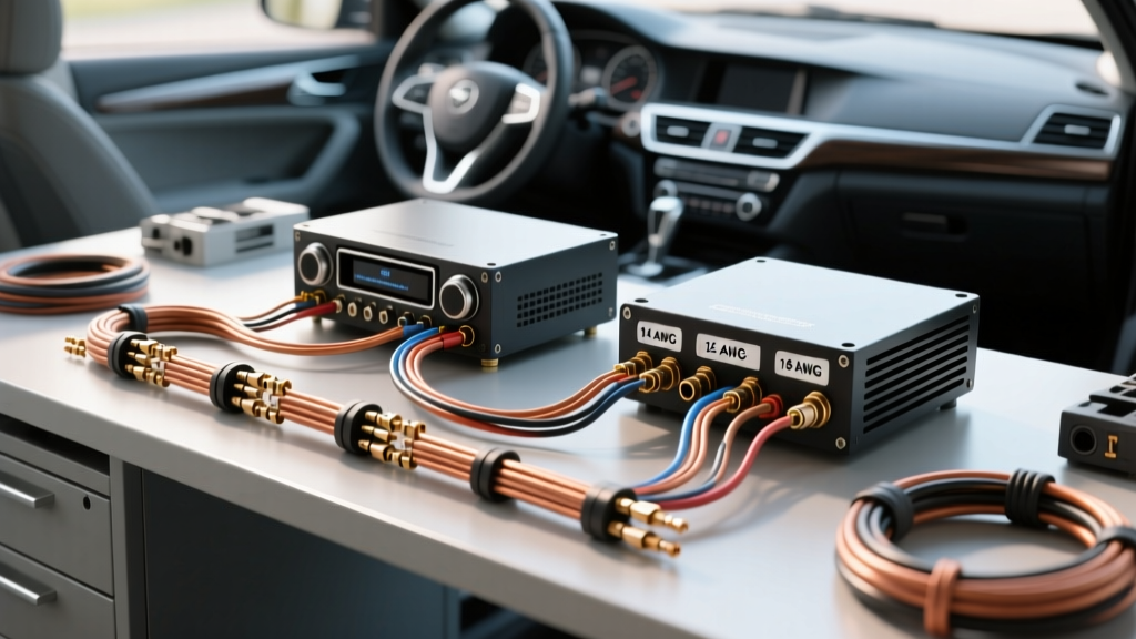
When consulting a standard wiring diagram for head unit installations, most DIYers focus solely on speaker outputs, RCA interconnects, and main power grounds. However, modern vehicle infotainment systems and high-end aftermarket receivers frequently interface with 12V DC motors. Whether you are integrating a motorized power antenna, a flip-out touchscreen display, motorized equalizer sliders, or an external amplifier cooling fan, treating these accessories as simple resistive loads is a critical mistake. Motors are highly inductive. They draw massive inrush currents and generate destructive back-electromotive force (back-EMF) when switched off. In 2026, with ultra-sensitive Digital Signal Processing (DSP) receivers like the Sony Mobile ES series or Alpine F#1 Status dominating the market, protecting low-voltage trigger circuits from motor-induced voltage spikes is more important than ever.
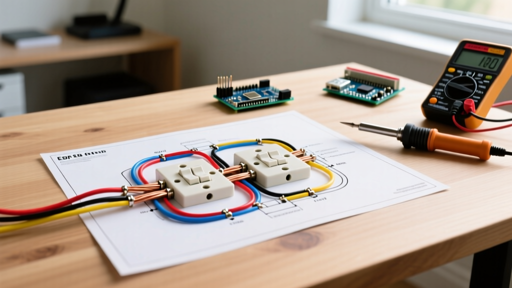
This comprehensive motor wiring tutorial will walk you through the exact pinouts, relay integration, and flyback diode placement required to safely wire motorized accessories to your head unit without frying its internal PCB traces.
Standard Wiring Diagram for Head Unit Pinouts
Before wiring any motorized accessory, you must identify the correct trigger and power sources. The EIA/CEA-12V standard dictates the color-coding for aftermarket head unit harnesses. Below is the essential pinout reference you need for motor integration.
| Wire Color | Function | Motor Wiring Application | Max Current Capacity |
|---|---|---|---|
| Yellow | Constant 12V (Memory) | Direct power for motor memory positions (e.g., seat/memory EQ) | 5A - 10A (Fused) |
| Red | Switched 12V (Ignition) | Primary power feed for accessory relays | 5A - 10A (Fused) |
| Black | Chassis Ground | Motor ground return path | Main Fuse Rating |
| Blue | Power Antenna Trigger | Signal to raise/lower motorized mast antennas | 300mA (Strict Limit) |
| Blue/White | Amplifier Turn-On | Trigger for motorized amp cooling fans | 300mA - 500mA |
CRITICAL WARNING: The blue and blue/white wires on a head unit harness are strictly signal wires. They output a maximum of 300mA to 500mA. Attempting to wire a 12V DC motor directly to these wires will instantly vaporize the internal copper traces on the head unit's motherboard, resulting in a $400+ replacement cost.
Motor Wiring Tutorial: Managing Inductive Loads
To properly integrate motors into your car audio system, we must apply fundamental motor wiring principles. When a DC motor spins, it builds a magnetic field. When the head unit cuts the power (e.g., turning off the ignition or retracting the antenna), that magnetic field collapses rapidly, sending a high-voltage spike (often exceeding 50V) back down the wire. This is known as inductive kickback.
Scenario 1: The Power Antenna Motor
Standard aftermarket power antennas (such as the Metra 44-PW22 or OEM Honda/Acura replacements) draw between 3 to 5 amps during startup and 1 to 2 amps while running. Because the head unit's blue wire can only supply 0.3 amps, you must use the blue wire strictly as a low-current trigger for an automotive relay, which then switches the high-current 12V power to the motor.
Scenario 2: Motorized Flip-Out Screens and Amplifier Fans
Flip-out screens utilize micro-DC gear motors that require polarity reversal to open and close. These are typically managed by the head unit's internal H-bridge motor driver. However, if you are adding external motorized amplifier cooling fans (like the PAC FAN-1), you will use the Blue/White amplifier turn-on wire to trigger a relay that powers the fan motor directly from the battery.
Step-by-Step Relay Wiring for Motor Protection
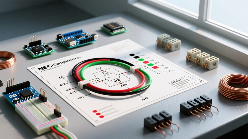
To protect your equipment, you will need a standard Bosch-style 5-pin 12V automotive relay (e.g., Tyco V23234-A6001-A800, typically priced between $4.50 and $8.00) and an inline fuse holder. According to guidelines from the Mobile Electronics Certification Program (MECP), all high-current motor circuits must be fused within 18 inches of the power source.
- Pin 30 (Common): Connect to a fused 12V constant power source (use 14 AWG wire and a 10A inline ATC fuse tapped near the battery or main distribution block).
- Pin 87 (Normally Open): Connect to the positive terminal of your 12V DC motor (e.g., the power antenna motor).
- Pin 86 (Coil Positive): Connect to the head unit's Blue (Antenna) or Blue/White (Amp Turn-on) trigger wire using 18 AWG wire.
- Pin 85 (Coil Negative): Connect to a clean, bare-metal chassis ground point.
- Pin 87a (Normally Closed): Leave this pin empty and insulated for standard on/off motor applications.
- Motor Ground: Connect the negative terminal of the motor directly to the chassis ground using 14 AWG wire.
Advanced Troubleshooting: Flyback Diodes and PWM
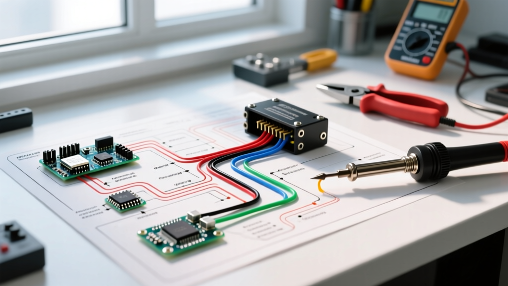
Even with a relay, the inductive spike from the motor can arc across the relay contacts or feed back into the vehicle's CAN bus system, causing erratic behavior in modern 2026 vehicle infotainment networks. To solve this, we install a flyback diode.
Using a standard 1N4007 rectifier diode (costing less than $0.10 per unit), solder it directly across the motor's positive and negative terminals. The silver stripe on the diode must face the positive terminal. When the motor shuts off and generates a reverse voltage spike, the diode creates a closed loop, allowing the spike to dissipate safely as heat within the motor windings rather than traveling back to the relay or head unit.
Wire Gauge & Voltage Drop Matrix
Motors are highly sensitive to voltage drop. If the voltage at the motor terminals drops below 10.5V under load, the motor will stall, draw excessive amperage, and overheat. The SAE J1128 standard for Low Tension Primary Cable outlines the thermal and conductivity requirements for automotive wiring. Use the matrix below to select the correct American Wire Gauge (AWG) based on your motor's run length and amperage.
| Motor Draw (Amps) | 0 - 10 ft Run | 10 - 20 ft Run | 20 - 30 ft Run |
|---|---|---|---|
| 1A - 3A (Cooling Fans) | 18 AWG | 16 AWG | 14 AWG |
| 3A - 6A (Power Antennas) | 16 AWG | 14 AWG | 12 AWG |
| 6A - 10A (Winch/Heavy Motors) | 12 AWG | 10 AWG | 8 AWG |
2026 DSP Head Units and Digital Motor Control
In 2026, high-end DSP head units utilize advanced power management ICs (PMICs) that monitor the current draw on the Blue/White trigger wire. If the PMIC detects an anomaly—such as the micro-arcing caused by a failing motor relay coil—it will electronically shut down the trigger output to protect the DSP processor. If your motorized accessories suddenly stop responding after a few weeks of use, but the head unit still powers on, you likely have a failing relay coil or a missing flyback diode causing the PMIC to trip its internal protection mode. Replacing the relay and adding a 1N4007 diode across the relay coil (Pin 85 to Pin 86) will usually resolve this issue instantly.
Frequently Asked Questions
Can I use the power antenna wire to turn on an amplifier?
While both the Blue (Power Antenna) and Blue/White (Amp Turn-On) wires provide a 12V signal, the Blue wire is often programmed to drop to 0V when the head unit switches to CD or Aux mode on older models. For amplifiers and motorized cooling fans, always use the Blue/White wire to ensure the accessory remains powered across all audio sources.
My motorized antenna goes up, but won't come down. Why?
This is a classic polarity issue. Standard power antennas require a constant 12V feed to raise the mast, and a separate 12V feed to the "down" circuit to retract it. If you are using a standard ISO harness, ensure the head unit's automated logic is compatible with your specific antenna's 3-wire or 5-wire control module. Consult the Crutchfield Learning Center for vehicle-specific antenna logic diagrams.
Do I need a relay for a motorized LED equalizer?
If the motorized EQ draws less than 250mA, you can wire it directly to the Blue/White trigger wire. However, if it features incandescent bulbs or high-draw stepper motors, a relay is mandatory to prevent overloading the head unit's surface-mount transistors.