
Integrating Turn Signals with Your Main Breaker Panel
When restoring a classic vehicle, building a custom hot rod, or upgrading a fleet truck, the turn signal circuit is often treated as an afterthought. However, as modern automotive electrical systems grow more complex, properly integrating your lighting into the main fuse and breaker panel is critical. A poorly designed circuit can lead to hyper-flashing, voltage drops, or catastrophic wire meltdowns. Understanding the wiring diagram for turn signals from a panel and breaker perspective ensures your circuit protection matches the actual current draw and wire gauge of your system.
In this comprehensive guide, we break down the anatomy of the turn signal circuit, how to size your fuses and breakers, and the specific hardware you need for a bulletproof installation in 2026.
Anatomy of the Turn Signal Circuit
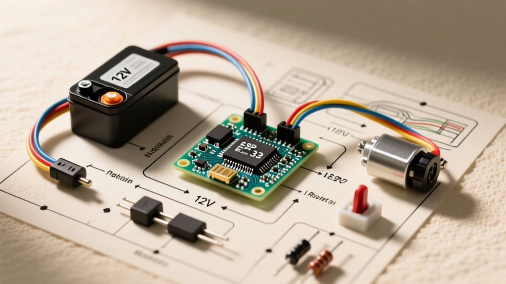
Before routing wires to your breaker box, you must understand the logical flow of the circuit. A standard automotive turn signal system operates on a 12V DC negative-ground architecture. The current flows through the following sequence:
- Power Source: Battery positive terminal to the main fuse panel bus bar.
- Circuit Protection: A dedicated blade fuse or thermal breaker (typically 10A to 15A).
- Ignition Interlock (Optional): Some diagrams route power through the ignition switch so signals only operate when the key is in the 'Run' or 'Accessory' position.
- Flasher Relay: An electro-mechanical or solid-state module that interrupts the circuit to create the blinking effect.
- Directional Switch: The steering column stalk that diverts current to either the left or right circuit.
- Load (Bulbs): Front and rear indicator lamps.
- Ground: Return path to the chassis and back to the battery negative.
Breaker and Fuse Sizing for the Panel
The most common mistake DIYers make is oversizing the breaker or fuse 'just to be safe.' In reality, a fuse is designed to protect the wire, not the component. If you run 18 AWG wire but protect it with a 20A breaker, the wire will melt and potentially ignite a fire long before the breaker trips.
According to Blue Sea Systems' Circuit Protection Guidelines, the overcurrent protection device (OCPD) must be rated at or below the maximum continuous current-carrying capacity of the smallest wire in the circuit.
Wire Gauge vs. Breaker Sizing Matrix (12V Systems)
| Wire Gauge (SAE J1128 TXL) | Max Ampacity (Engine Bay) | Recommended ATC/ATO Fuse | Max Incandescent Load (1157 Bulbs) |
|---|---|---|---|
| 16 AWG | 10 Amps | 7.5A or 10A | 4 Bulbs (approx. 8.4A) |
| 14 AWG | 15 Amps | 10A or 15A | 6 Bulbs (approx. 12.6A) |
| 12 AWG | 20 Amps | 15A or 20A | 8+ Bulbs / Trailer Towing |
Expert Note: When towing a trailer, the additional four trailer bulbs add roughly 8 amps to the circuit. You must upgrade to 12 AWG primary wire and a 20A breaker, or install a dedicated trailer lighting relay to isolate the load from the vehicle's main turn signal breaker.
Interpreting the Wiring Diagram for Turn Signals
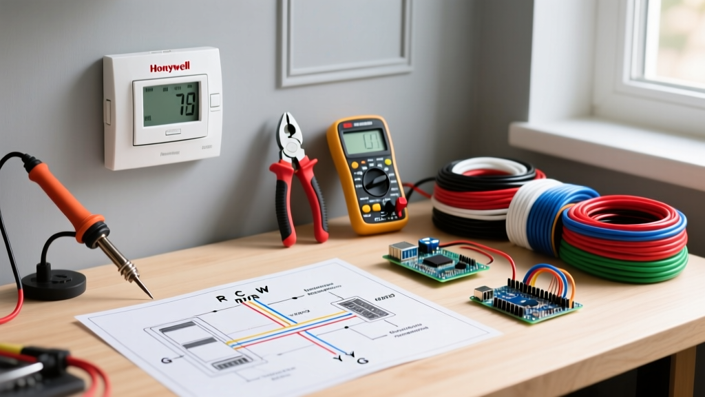
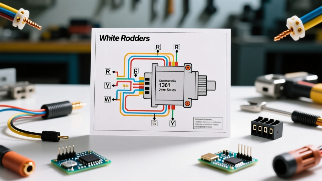
When reading a schematic, the turn signal switch is usually depicted as a multi-pole, double-throw (MPDT) switch. The center pole receives switched 12V power from the flasher relay. The two outer poles route power to the left and right indicator wires.
Standard SAE wire color codes dictate that the Left Turn signal is typically Light Green and the Right Turn signal is Dark Green (or sometimes Yellow/White depending on the manufacturer, such as GM vs. Ford). Always verify with a multimeter rather than trusting faded, 40-year-old wiring.
Selecting the Right Fuse Block
As of 2026, the industry standard for custom panels is the negative-bus integrated fuse block. A high-quality 12-circuit ST Blade fuse block from Blue Sea Systems retails for approximately $55 to $75. These blocks feature independent negative bus bars for each circuit, eliminating the need to daisy-chain ground wires to the chassis, which drastically reduces ground-loop interference and voltage drop.
The Flasher Relay: Thermal vs. Solid-State
The flasher relay is the heartbeat of the turn signal circuit. Its placement in the wiring diagram is critical: it must sit upstream of the turn signal switch but downstream of the fuse.
Thermal Flashers (OEM Style)
Older thermal flashers (like the standard Tridon 552) rely on a bimetallic strip that heats up and bends to break the circuit. They require a minimum current draw (usually 4 to 6 amps) to generate enough heat to function. If a bulb burns out, the current drops, and the flasher stops blinking—a built-in failure warning.
Solid-State LED Flashers
If you are upgrading to LED bulbs (which draw a mere 0.2A per bulb), a thermal flasher will not work, resulting in 'hyper-flashing' or no flashing at all. You must install an electronic, solid-state relay like the Novita Technologies EP35 or a Littelfuse Smart Relay. These use an internal microchip and MOSFET to time the flashes regardless of the current draw. When integrating this into your panel, ensure the relay is wired to a switched ignition source so it doesn't draw parasitic micro-currents that drain the battery over weeks of storage.
Step-by-Step Panel Integration & Routing
To execute the wiring diagram for turn signals flawlessly, follow these professional installation steps:
- Step 1: Crimping. Never use solder-only connections in high-vibration automotive environments. Solder wicks into the wire strands, creating a rigid point that snaps under vibration. Use an open-barrel crimp tool (like the Titan 11500) with adhesive-lined heat shrink terminals.
- Step 2: Routing. Run your 14 AWG TXL wire from the fuse panel through the firewall using a dedicated rubber grommet. Keep signal wires at least 2 inches away from high-current alternator charging wires to prevent electromagnetic interference (EMI).
- Step 3: Grounding. The ground connection is where 90% of turn signal failures occur. Do not ground to painted sheet metal. Use a 12 AWG ground wire bolted directly to a clean, bare metal chassis point, sealed with dielectric grease to prevent corrosion.
Common Failure Modes & Troubleshooting
Even with a perfect wiring diagram for turn signals, real-world conditions introduce variables. Here is how to troubleshoot the most common panel-related issues:
1. Voltage Drop Across the Fuse Block
If your turn signals blink slowly or appear dim, you likely have voltage drop. Using a digital multimeter (such as the Fluke 87V, currently priced around $450), set it to DC Volts. Place the red probe on the battery positive and the black probe on the load side of the turn signal fuse. A reading above 0.2V indicates a corroded fuse blade or a failing bus bar internal to the panel. According to Mouser Electronics' Littelfuse specifications, ATC fuses should maintain a millivolt drop of less than 150mV at rated current.
2. Backfeeding and 'Four-Way Flash' Syndrome
If activating the left turn signal causes the right dash indicator to glow dimly, you have a backfeed issue. This is almost always caused by a bad ground at the rear tail light housing. The current seeks an alternative path to ground, traveling backward through the opposite bulb's filament. Fix this by running dedicated ground wires from each tail light housing back to a central ground bus bar, rather than relying on the vehicle's rusted chassis.
3. Thermal Breaker Fatigue
If you opted for an auto-resetting thermal circuit breaker instead of a standard blade fuse, be aware of thermal fatigue. In high ambient engine bay temperatures (exceeding 180°F), a 15A thermal breaker may trip prematurely at 12A. For under-hood fuse panels, always use standard ATC/ATO blade fuses, as their element is sealed and less susceptible to ambient air temperature fluctuations.
Expert FAQ
Q: Can I use a single 20A breaker for both the turn signals and the hazard flashers?
A: While they share the same physical bulbs, the hazard switch typically draws power directly from the battery (constant 12V) so it works with the key off, while turn signals use switched 12V. It is best practice to use two separate fuses in your panel: a 15A for hazards (constant) and a 10A for turn signals (switched).
Q: Do I need load resistors if I use an LED flasher relay?
A: No. The entire purpose of an electronic LED flasher relay is to eliminate the need for 50W load resistors. Load resistors generate massive amounts of heat and waste energy. Always choose the electronic relay route for modern panel builds.
Q: What wire type should I buy for the panel-to-switch run?
A: Avoid generic PVC 'primary wire' from big-box stores. Purchase SAE J1128 TXL or GXL wire. TXL features cross-linked polyethylene insulation, which is highly resistant to engine bay heat, abrasion, and chemical exposure, ensuring your wiring diagram translates into a lifetime installation.