
The Anatomy of an RV Electrical Wiring Diagram
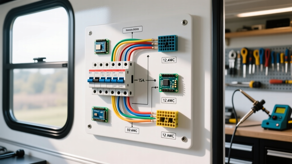
Interpreting an RV electrical wiring diagram requires understanding the fundamental split between alternating current (AC) and direct current (DC) systems. Unlike a standard residential home that relies solely on 120V/240V AC, a recreational vehicle operates a dual-voltage ecosystem. The main distribution panel—often called a power center—acts as the central nervous system, routing 120V AC power from shore power or a generator, and 12V DC power from the battery bank or solar charge controller.
When you unroll a manufacturer schematic, you will typically see the AC distribution on the left side and the DC distribution on the right. The AC side utilizes thermal-magnetic circuit breakers, while the DC side relies on automotive-style blade fuses or DC-rated circuit breakers. Tracing these circuits accurately is critical for troubleshooting dead outlets, diagnosing parasitic draws, or safely upgrading your rig for modern high-draw appliances like induction cooktops or lithium-compatible air conditioners.
AC vs. DC Power Distribution Paths
The 120V AC path begins at the shore power inlet (typically a 30-amp NEMA TT-30R or a 50-amp NEMA 14-50R). From there, it passes through a main breaker before splitting to branch breakers. The DC path originates at the battery disconnect switch, flows through a high-amperage main fuse (usually 40A to 80A), and enters the DC fuse block. A crucial component bridging these two systems is the power converter/charger, which steps down 120V AC to 13.6V DC to charge the batteries and run DC loads while plugged in.
Decoding the Breaker Panel: AC and DC Sizing
One of the most common mistakes DIYers make when modifying an RV is mismatching the breaker size to the wire gauge. An RV electrical wiring diagram will specify the exact American Wire Gauge (AWG) required for each circuit. Over-fusing a circuit—such as placing a 20A breaker on a 14 AWG wire—creates a severe fire hazard, as the wire will melt before the breaker trips.
| System | Breaker/Fuse Size | Min. Wire Gauge (AWG) | Max Continuous Wattage | Typical RV Application |
|---|---|---|---|---|
| 120V AC | 15 Amp | 14 AWG | 1,440W | Entertainment center, GFCI outlets |
| 120V AC | 20 Amp | 12 AWG | 1,920W | Microwave, roof AC unit #1 |
| 120V AC | 30 Amp | 10 AWG | 2,880W | Second roof AC, water heater |
| 12V DC | 15 Amp | 14 AWG (Short runs) | 180W | Interior LED lighting, water pump |
| 12V DC | 20 Amp | 12 AWG | 240W | Slide-out motors, vent fans |
| 12V DC | 30 Amp | 10 AWG | 360W | 12V compressor fridges, inverters |
Step-by-Step: Tracing a Circuit on Your RV Diagram
When a specific appliance fails, use this systematic approach to trace the circuit on your schematic:
- Identify the Load: Locate the specific appliance (e.g., 'Microwave') on the diagram and note its designated branch breaker number (e.g., CB2).
- Check the Power Source: Verify if the appliance requires 120V AC or 12V DC. For AC, ensure the main shore breaker and the specific branch breaker are in the 'ON' position.
- Trace the Hot Wire: Follow the solid black (AC) or red (DC) line from the breaker to the appliance. Note any intermediate junction boxes, splices, or relays.
- Trace the Neutral/Ground: Follow the white (AC neutral) or white/black (DC ground) line back to the respective neutral bus bar or chassis ground point. A loose neutral is a leading cause of RV electrical failures.
- Test at Intervals: Use a digital multimeter to test for voltage at the breaker terminal, the first junction point, and finally at the appliance terminal block to isolate the break.
Shore Power Integration: The 50-Amp NEMA 14-50R Standard
Modern fifth wheels and large motorhomes predominantly use the 50-amp NEMA 14-50R shore power configuration. Your RV electrical wiring diagram will show this as a 4-wire system delivering split-phase 120/240V power. The four prongs are designated as X (Hot 1, 120V), Y (Hot 2, 120V), W (Neutral), and G (Ground).
Inside the RV's main panel, the X and Y hot legs are distributed across separate branch breakers to balance the load. If you are upgrading an older 30-amp rig to a 50-amp system, you must replace the main power cord, the inlet, and the entire distribution panel. The neutral bus bar must be rated for at least 100 amps to handle the combined return current from both hot legs, and all terminal lugs must be torqued to the manufacturer's specifications—typically 45 in-lbs for 12-10 AWG wires and up to 120 in-lbs for larger gauge feeds.
Common RV Panel Failure Modes and Troubleshooting
Expert Warning: DC Thermal Runaway
Unlike AC breakers that trip thermally, standard automotive blade fuses used in RV DC panels rely on the fuse element melting. If a fuse block terminal becomes loose, the increased resistance generates heat. This heat can prematurely melt the fuse element or, worse, deform the plastic housing, leading to a high-resistance connection that causes voltage drop and potential thermal runaway. Always use a thermal camera to scan your DC fuse block under heavy load to identify hot spots.
Another frequent issue is voltage drop on the DC side. Because 12V systems operate at a much lower voltage, even a small drop in voltage represents a significant percentage of power loss. The formula for voltage drop is VD = (2 x K x I x L) / CM, where K is the resistivity of copper (12.9), I is current, L is one-way wire length, and CM is the circular mils of the wire. If your 12V compressor fridge is 30 feet from the battery panel, a 10 AWG wire will experience a 2.5% voltage drop at 15 amps. To maintain optimal efficiency and prevent the fridge's low-voltage cutoff from triggering, upgrading to 8 AWG wire is highly recommended.
2026 Panel Upgrades: Equipment and Pricing
If your rig's schematic reveals an outdated, fused-only AC panel or a corroded DC block, a comprehensive upgrade is necessary to meet modern safety standards. Here are the industry-standard components for 2026:
- Progressive Dynamics PD4560K1CSV Power Center ($295 - $320): This all-in-one unit replaces both the AC breaker panel and DC fuse block, while integrating a 60-amp lithium-compatible smart charger. It features 8 AC breaker spaces and 12 DC fuse positions, making it the gold standard for travel trailer rewiring.
- Blue Sea Systems 5025 ST Blade Fuse Block ($38 - $45): For auxiliary DC circuits (like adding solar lighting or a secondary water pump), this 6-circuit fuse block features independent negative buses and tin-plated copper buses for maximum corrosion resistance.
- Siemens QAF2 AFCI Breakers ($45 - $60 each): Modern RVIA standards increasingly mandate Arc Fault Circuit Interrupters (AFCI) for bedroom circuits and Ground Fault Circuit Interrupters (GFCI) for kitchen and bathroom outlets to prevent electrical fires and shocks in damp environments.
Safety Codes and RVIA Compliance
Any modification to your RV's electrical system must adhere to strict safety codes. The Recreation Vehicle Industry Association (RVIA) mandates that all certified RVs comply with NFPA 1192 (Standard on Recreational Vehicles). Furthermore, the AC wiring methods must align with NFPA 70 (National Electrical Code) Article 551, which specifically governs recreational vehicles and RV parks.
Key compliance rules include maintaining a strict separation between AC and DC wiring (they must not share the same conduit or junction box), ensuring all chassis grounds are bonded to the main grounding bus, and using only stranded copper wire rated for at least 90°C (THHN/THWN) in high-temperature zones near the engine or exhaust. For detailed circuit protection selection, the Blue Sea Systems Circuit Protection Guide offers invaluable ampacity derating charts based on ambient engine bay temperatures.
Frequently Asked Questions
Can I use residential Romex (NM-B) wire in my RV?
No. NM-B wire uses solid copper conductors which are prone to work-hardening and snapping due to the constant vibration of highway travel. RV electrical wiring diagrams exclusively specify stranded copper wire (like THHN/THWN or MTW) to withstand mechanical stress.
Why does my RV diagram show two separate ground bus bars?
One bus bar is for the AC safety ground (bonded to the shore power ground pin and the RV chassis), and the other is for the DC negative returns. While they are ultimately bonded together at the main chassis ground point, keeping the branch wiring separated prevents AC fault currents from traveling through smaller DC ground wires.