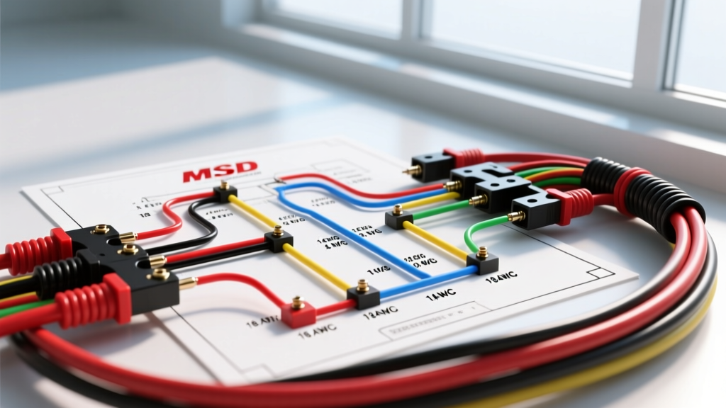

The Anatomy of MSD Capacitive Discharge Wiring
Upgrading to a Capacitive Discharge (CD) ignition system is one of the most effective ways to eliminate high-RPM misfires and improve throttle response in both carbureted and early EFI engines. However, the effectiveness of the MSD Performance hardware relies entirely on the integrity of its electrical connections. A proper wiring diagram for MSD ignition units—specifically the ubiquitous MSD 6A (Part #5510) and MSD 6AL (Part #5520)—is not just a suggestion; it is a strict electrical blueprint.
As of 2026, modern engine bays are increasingly congested with high-output alternators, electric water pumps, and CAN-bus networks. This dense electromagnetic environment means that guessing wire gauges or ignoring color-coded trigger circuits will inevitably lead to voltage drop, EMI (Electromagnetic Interference) feedback, and catastrophic misfires. This guide decodes the exact wire gauge requirements, color code matrices, and routing protocols necessary to execute a flawless MSD installation.
MSD 6-Series Wire Color Code & Gauge Reference Matrix
MSD utilizes a standardized color-code system across its analog 6-Series lineup. The primary mistake DIYers make is treating all wires as equal. Signal wires require shielding and twisting, while power wires demand high-strand-count copper to handle massive transient current spikes. Refer to the matrix below before cutting a single wire.
| Wire Color | Function / Destination | Minimum Wire Gauge | Required Wire Type / Topology |
|---|---|---|---|
| Heavy Red | Main +12V Battery Power | 8 AWG (10 AWG absolute min) | Stranded Copper (TXL or GXL insulation) |
| Heavy Black | Main Chassis/Battery Ground | 8 AWG (10 AWG absolute min) | Stranded Copper (TXL or GXL insulation) |
| Orange | Coil Positive (+) Primary | 12 AWG or 14 AWG | High-Temp Stranded (PTFE/Tefzel preferred) |
| Black (Light) | Coil Negative (-) Primary | 12 AWG or 14 AWG | High-Temp Stranded (PTFE/Tefzel preferred) |
| Red (Light) | +12V Switched (Ignition ON) | 16 AWG or 18 AWG | Standard Stranded Automotive Wire |
| White | Points / Amplifier Trigger | 18 AWG | Standard Stranded (Unshielded acceptable) |
| Violet | Magnetic Pickup (+) | 18 AWG to 20 AWG | Shielded Twisted-Pair (with Green) |
| Green | Magnetic Pickup (-) | 18 AWG to 20 AWG | Shielded Twisted-Pair (with Violet) |
Executing the Power and Ground Circuit (The 8 AWG Mandate)
The most critical aspect of any wiring diagram for MSD ignition setups is the main power and ground loop. During a spark event, the MSD box draws a continuous 1 to 2 amps, but the transient peak current drawn from the capacitor bank can spike dramatically. If you use standard 14 AWG or 12 AWG wire for the Heavy Red and Heavy Black connections, you will introduce resistance.
The Voltage Drop Threshold
According to Society of Automotive Engineers (SAE) guidelines, high-current automotive circuits should not exceed a 0.2V drop under load. To test this:
- Set your Digital Multimeter (DMM) to DC Voltage.
- Place the red probe directly on the MSD's Heavy Red terminal and the black probe on the battery's positive post.
- Have an assistant crank the engine or rev it to 4,000 RPM.
- If the DMM reads higher than 0.2V, your wire gauge is too small, or your crimp terminals are oxidized. The MSD internal oscillator will reset under this voltage sag, causing a dead miss.
Terminal Crimping vs. Soldering in High-Vibration Zones
Never solder the heavy 8 AWG ring terminals that connect to the battery or chassis. Solder is brittle and will fatigue-crack under engine vibration, leading to a sudden loss of ignition. Instead, use a Delphi/Packard-style open-barrel crimper or a high-quality hex-crimp tool, followed by dual-wall adhesive-lined heat shrink. This creates a gas-tight, weatherproof seal that resists engine bay corrosion.
Trigger Circuit Topologies: Points, Amplifier, and Magnetic Pickup
The MSD 6-Series is versatile, offering three distinct trigger methods. Your wiring execution must match the specific trigger hardware installed on your distributor.
1. The White Wire (Points or Electronic Amplifier Trigger)
If you are running a traditional breaker-point distributor or an external transistorized amplifier (like a Ford Duraspark or GM HEI module), you will use the White wire. The White wire triggers the MSD box when it sees a ground connection (points closing) or a voltage drop (amplifier switching). Keep this wire routed away from the exhaust headers, as heat degradation on the 18 AWG insulation can expose the conductor and cause a short to ground, firing the coil randomly.
2. The Violet and Green Wires (Magnetic Pickup Trigger)
For aftermarket billet distributors utilizing a magnetic pickup (reluctor and stator), the Violet (+) and Green (-) wires are mandatory. This is where EMI becomes a severe threat in 2026 engine bays. Alternators and fuel injector harnesses emit high-frequency noise that the MSD box can interpret as a false trigger signal, causing the engine to backfire or advance timing erratically.
Expert EMI Shielding Protocol: The Violet and Green wires must be routed as a Shielded Twisted-Pair. Twist the two wires together at a rate of 4 to 6 twists per inch. The metallic shield drain wire must be grounded only at the MSD box end, leaving the distributor end floating. Grounding both ends creates a ground loop, turning your shield into an antenna that absorbs alternator whine.
Coil Primary Wiring: Managing the Inductive Kickback
The Orange wire connects to the Coil Positive (+) terminal, and the Light Black wire connects to the Coil Negative (-) terminal. The MSD box outputs a massive 400+ volts to the coil's primary winding, which the coil then multiplies into 40,000+ volts for the spark plug.
Do not use standard 18 AWG radio wire for the Orange and Black coil connections. The high-frequency, high-voltage square wave generated by the CD box will melt thin insulation over time and cause arc-tracking across the coil cap. Use 12 AWG or 14 AWG wire with PTFE (Tefzel) or high-grade silicone insulation. Furthermore, ensure these wires are kept at least two inches away from the engine block and fuel lines to prevent capacitive coupling and radio frequency interference (RFI).
2026 Troubleshooting Matrix: Common MSD Wiring Failure Modes
Even with a perfect wiring diagram for MSD ignition reference, physical routing errors can mimic internal component failures. Use this diagnostic matrix before assuming your CD box is defective.
| Symptom | Probable Wiring Root Cause | Diagnostic Fix & Action |
|---|---|---|
| Engine backfires through carb at high RPM | Violet/Green wires picking up EMI from alternator or EFI harness. | Verify twisted-pair routing. Ensure shield drain wire is grounded only at the MSD box. Reroute away from alternator. |
| Dead misfire above 5,500 RPM | Voltage drop on Heavy Red/Black wires starving the internal capacitor bank. | Perform DMM voltage drop test under load. Upgrade to true 8 AWG high-strand wire. Clean chassis ground points to bare metal. |
| Engine runs on with key OFF | Light Red (Switched +12V) wire connected to a "backfeed" circuit or generator warning lamp circuit. | Reroute Light Red wire to a clean, dedicated ignition-switched relay. Do not tap into the alternator exciter wire. |
| Coil arcs to ground or melts | Using undersized wire for Orange/Black coil primaries, or coil resistance is mismatched. | Verify 12 AWG wire. Ensure you are using a low-resistance CD-specific coil (e.g., MSD Blaster SS, 0.02 ohms primary). |
Expert FAQ on MSD Wiring Nuances
Can I use a relay for the Heavy Red power wire?
No. The Heavy Red wire should be connected directly to the battery positive terminal (with an inline ANL fuse or Maxi-Fuse rated for 20A-30A) or a dedicated, high-amperage marine-grade busbar. Introducing a standard 30A automotive relay into the main power loop adds internal contact resistance, which will cause voltage sag during peak capacitive discharge.
Where should the Light Red (+12V Switched) wire be connected?
The Light Red wire tells the MSD box to "wake up" when the key is turned to the ON position. It draws less than 1 amp. Connect it to the output side of your ignition switch, or ideally, use it to trigger a secondary relay that supplies clean, switched power directly from the battery. Avoid tapping into the wiper motor, radio, or choke circuits, as voltage fluctuations in these accessories will cause the MSD box to reset.
Does the MSD box need to be grounded to the engine block?
Absolutely not. The MSD case is isolated, and the Heavy Black wire handles all grounding. Furthermore, grounding the MSD chassis to the engine block can introduce severe ground-loop noise from the starter motor and alternator. Mount the box to the firewall or inner fender using stainless steel hardware, and rely solely on the 8 AWG Heavy Black wire routed directly to the battery negative terminal or a verified clean chassis ground point.
For further technical specifications and to verify compatibility with modern Holley Ignition Products, always consult the manufacturer's latest revision sheets. Proper wire gauge selection and meticulous attention to color-code routing are what separate a reliable, high-horsepower ignition system from a frustrating trailered vehicle.