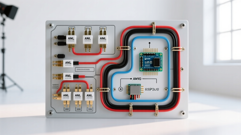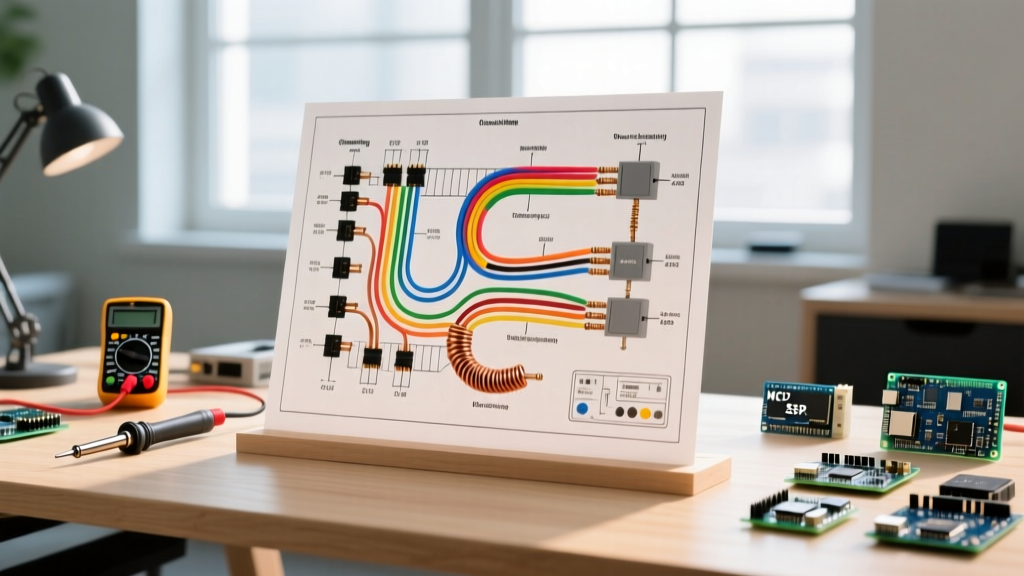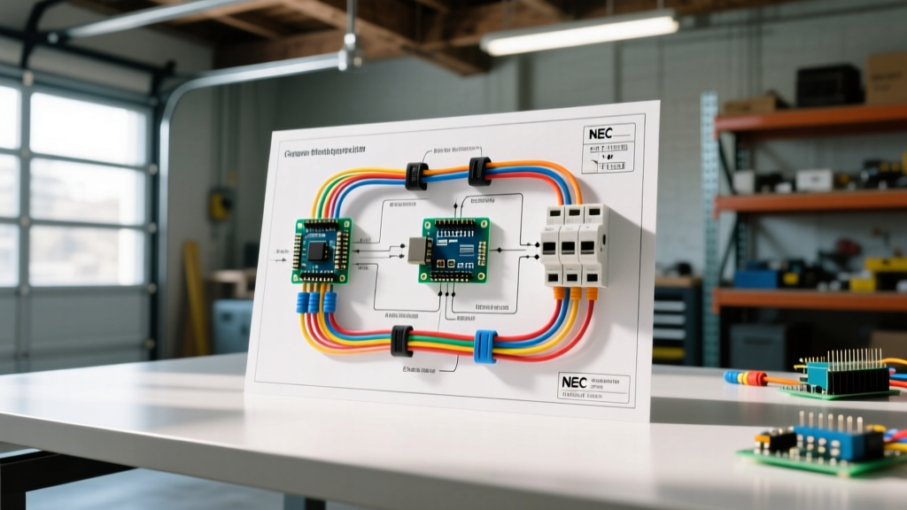

The Panel-to-Sensor Power Path: High Voltage Meets Low Voltage
When homeowners and DIYers search for a wiring diagram for garage door sensors, they often overlook the critical first step: the high-voltage branch circuit originating from the main electrical panel. Garage door openers act as the step-down transformers for the low-voltage photoelectric eyes (sensors) located near the floor. If the 120V panel circuit is improperly sized, suffers from severe voltage drop, or trips due to outdated breaker technology, your low-voltage sensor diagram becomes irrelevant. This guide bridges the gap between your main breaker panel and the delicate 5V to 12V DC sensor wiring, ensuring your system meets both operational and safety standards in 2026.
Breaker Sizing and NEC Garage Circuit Requirements
Before touching the low-voltage sensor wires, you must verify the high-voltage supply. According to the National Fire Protection Association (NFPA) and the National Electrical Code (NEC), garage receptacles have strict protection requirements that directly impact your opener's power stability.
- Circuit Sizing: A modern garage door opener (e.g., Chamberlain B970T or LiftMaster 8500W) requires a dedicated 15-amp or 20-amp 120V circuit. Do not share this circuit with heavy-draw garage appliances like air compressors or secondary freezers, as voltage sags during compressor startup can cause the opener's internal logic board to reboot, severing power to the sensors momentarily.
- GFCI and AFCI Protection: As of the 2023 and 2026 NEC cycles, 125V, 15A, and 20A receptacles in garages require Ground-Fault Circuit Interrupter (GFCI) protection. Furthermore, many jurisdictions now mandate Arc-Fault Circuit Interrupter (AFCI) protection for garage branch circuits. The most reliable solution from the panel is installing a dual-function (CAFCI/GFCI) 15A or 20A breaker directly in the main panel, rather than relying on a downstream GFCI receptacle which can be prone to nuisance tripping from the opener's motor harmonics.
- Wire Gauge for the Branch Circuit: Use 14 AWG copper for a 15A breaker, or 12 AWG copper for a 20A breaker. If the run from the panel to the garage ceiling exceeds 75 feet, upgrade to 12 AWG even on a 15A breaker to mitigate voltage drop, ensuring the opener's internal transformer receives a stable 120V to properly step down to the sensor's required low voltage.
Step-by-Step Wiring Diagram for Garage Door Sensors
Once the panel breaker is confirmed stable, you can proceed to the low-voltage wiring. The exact wiring diagram for garage door sensors depends heavily on the manufacturer and the generation of the safety beam technology. Below are the two dominant architectures in the field.
1. Chamberlain / LiftMaster Security+ 2.0 (Digital Pulse Architecture)
Models manufactured after 2012 (using the 041-0136 or similar sensor kits) do not use a simple analog DC voltage. They use a proprietary digital pulse over a 2-wire system. This means polarity and wire matching are critical.
- Prep the Wire: Strip exactly 7/16-inch of insulation from the ends of the 22 AWG stranded bell wire. Stripping too much exposes copper to potential shorting against the metal track; stripping too little results in a loose terminal connection.
- Sending Sensor (Yellow LED): Connect the solid white wire to the White terminal on the back of the sensor. Connect the white wire with the black stripe to the Grey terminal.
- Receiving Sensor (Green LED): Repeat the exact same wire-to-terminal mapping. Solid white to White; striped white/black to Grey.
- Opener Terminal Block: At the motor head, insert the solid white wires into Terminal 2 (White). Insert the striped wires into Terminal 3 (Grey). Do not overtighten the set screws, as 22 AWG stranded wire will easily crush and sever.
2. Genie Safe-T-Beam & Legacy Analog Systems
Older Genie models (like the MachForce 4063) and legacy analog systems use a simple infrared beam powered by a steady low-voltage DC or AC current (typically 6V to 12V).
- Prep the Wire: Strip 1/4-inch of insulation from standard 2-conductor bell wire.
- Sensor Connections: Connect the red wire to the red terminal and the white (or black) wire to the white terminal on both the sender and receiver eyes.
- Opener Terminal Block: Connect the red wires to the designated 'Sensor' or 'Red' terminal on the opener logic board, and the white wires to the 'Common' or 'White' terminal. Unlike the digital Security+ 2.0 systems, analog systems are generally polarity-agnostic at the sensor head, but maintaining color consistency is vital for troubleshooting.
Safety Warning: The U.S. Consumer Product Safety Commission (CPSC) strictly enforces UL 325 entrapment protection standards. Never bypass the sensor terminals with a jumper wire to force a door closed. If the sensors fail, the door must be repaired, not circumvented, to prevent severe crush injuries or fatalities.
Sensor Wire Gauge Selection & Voltage Drop Matrix
A frequent edge-case failure in large or custom-built garages is sensor malfunction due to voltage drop over long wire runs. The standard 22 AWG bell wire included in the box is only rated for runs up to 30 feet. If your opener is mounted on a high ceiling or the sensors are located on an extended driveway ramp, you must upgrade the wire gauge.
| Total Wire Run Length (One Way) | Recommended Wire Gauge | Wire Type | Expected Voltage Drop (at 12V DC) |
|---|---|---|---|
| Under 15 Feet | 22 AWG | Stranded Bell Wire | < 0.2V (Negligible) |
| 15 to 30 Feet | 22 AWG | Stranded Bell Wire | 0.3V - 0.5V (Acceptable) |
| 30 to 50 Feet | 20 AWG | Stranded Thermostat Wire | 0.4V - 0.7V (Optimal) |
| 50 to 80 Feet | 18 AWG | Stranded Multi-Conductor | 0.5V - 0.9V (Required for stability) |
Note: For Chamberlain Security+ 2.0 digital systems, the logic board reads digital pulses rather than raw voltage thresholds, making them slightly more tolerant of voltage drop over 22 AWG wire than legacy analog Genie systems. However, upgrading to 20 AWG for runs over 30 feet remains the industry best practice to prevent signal degradation from electromagnetic interference (EMI).
Diagnostic LED Matrix: Troubleshooting Sensor Failures
When the door refuses to close and the wall console light flashes, the sensors are communicating a specific fault code via their integrated LEDs. Use this diagnostic matrix to isolate the issue without guessing.
| Sending Eye (Sender) LED | Receiving Eye (Receiver) LED | Diagnostic Meaning | Corrective Action |
|---|---|---|---|
| Solid Yellow | Solid Green | System Normal / Aligned | No action required. |
| Solid Yellow | Off or Flickering Green | Misalignment or Obstruction | Realign brackets. Ensure both lenses are exactly 4 to 6 inches above the floor and pointing directly at each other. |
| Off | Off | Open Circuit / No Power | Check panel breaker. Check for a severed wire near the track staples. Test voltage at the opener terminal block. |
| Flashing Yellow | Off | Short Circuit in Wiring | Inspect the entire wire run. A staple driven too deeply into the drywall has likely pinched the 22 AWG wires together, shorting the digital pulse. |
| Off | Flashing Green | Reverse Polarity (Digital Systems) | Swap the white and grey wires at the opener terminal block. Digital systems require strict polarity matching. |
Physical Routing and Edge Case Failures
Even with a perfect wiring diagram and a properly sized 20A dual-function breaker, physical installation errors will cause chronic sensor failures. Here are the most common edge cases encountered by master electricians and door technicians:
The 'Sunstrike' Interference
Photoelectric sensors operate on an infrared wavelength (typically 850nm to 940nm). If the garage faces west and the late afternoon sun shines directly into the receiving lens, the ambient IR radiation will blind the sensor, causing the door to reverse. Solution: Install opaque PVC pipe shields over the sensors or swap the sender/receiver sides so the receiving eye is shaded by the garage interior.
Staple-Induced Micro-Shorts
When routing the 22 AWG wire up the vertical track, DIYers often use a standard hammer stapler. The kinetic force of a heavy-duty staple easily crushes the thin insulation of bell wire, creating a micro-short that only manifests when the door vibrates during operation. Solution: Use insulated cable clips or a specialized low-voltage staple gun with a depth-guide to secure the wire to the drywall, keeping it at least 2 inches away from the moving track hardware.
UV Degradation of Wire Insulation
If the sensor wire is routed outside the garage door seal or exposed to direct sunlight in an open carport, standard PVC bell wire insulation will become brittle and crack within 18 months, leading to ground faults. Solution: For any exterior or semi-exposed runs, use UV-rated outdoor thermostat wire or run the low-voltage cable through a flexible liquid-tight non-metallic conduit (LFNC-B).
By treating the garage door sensor circuit as a complete system—starting from a properly sized, NEC-compliant breaker in the main panel and ending with precision low-voltage terminations at the floor—you ensure decades of safe, uninterrupted entrapment protection.