
The Blueprint for 4x4 Electrical Mods: Planning Your Jeep Wrangler Install
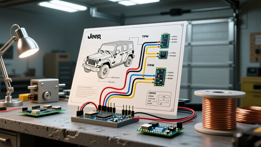
Modifying a Jeep Wrangler is a rite of passage for off-road enthusiasts, but modern Wranglers are far more complex than their carbureted ancestors. Whether you are outfitting a 2012 JK with a 12,000-lb winch or adding a 50-inch LED light bar to a 2024 JL, blindly splicing into factory harnesses is a recipe for catastrophic electrical failure. A standard wiring diagram for Jeep Wrangler models is not just a map of copper routes; it is a critical survival guide to navigating multiplexed networks, smart power modules, and Pulse Width Modulation (PWM) circuits.
This installation planning guide breaks down the architectural differences between the JK and JL generations, decodes factory connector pinouts, and provides actionable frameworks for sizing relays, selecting wire gauges, and bypassing CAN-bus protections without triggering dashboard error codes or frying your Body Control Module (BCM).
Architecture Shift: JK TIPM vs. JL Smart BCU
Before you strip a single wire, you must understand the power distribution architecture of your specific Wrangler generation. The transition from the JK (2007–2018) to the JL (2018–present) represented a massive leap in vehicle networking. Understanding this dictates how you read the wiring diagram for Jeep Wrangler circuits and where you can safely tap into power.
| Feature | Jeep Wrangler JK (2007-2018) | Jeep Wrangler JL (2018-Present) |
|---|---|---|
| Primary Power Hub | TIPM (Totally Integrated Power Module) | PDC (Power Distribution Center) & Smart BCU |
| Relay Logic | Hardwired internal relays (soldered) | Software-controlled solid-state FETs |
| Lighting Control | Standard 12V / PWM on later models | Strict PWM and CAN-bus current monitoring |
| Common Failure Mode | Internal TIPM fuel pump relay burnout | BCM circuit shutdown due to resistance spikes |
| Safe Tap Strategy | External relay triggered by ignition switch | PAC TR-450 CAN-bus harness or dedicated PDC fuse tap |
The JK TIPM Trap
In 2007–2011 JK models, the TIPM contains soldered-in micro-relays for critical systems like the fuel pump and wipers. If you tap into a factory headlight or accessory wire to trigger a high-draw relay coil, the voltage drop and resistance change can overheat the TIPM's internal circuitry. Planning Rule: Never use a JK factory lighting circuit to directly power aftermarket accessories. Use the factory wire only to trigger a low-draw external automotive relay (like a standard Bosch 30A 5-pin), or install a dedicated TIPM bypass harness.
The JL CAN-Bus Firewall
The JL generation utilizes a smart Body Control Module (BCM) that constantly monitors the current draw and resistance of every exterior lighting circuit. If you splice an LED light bar trigger wire directly into the factory fog light harness, the BCM will detect the altered resistance, assume a short circuit, and shut down the entire lighting bank. To bypass this, your installation plan must incorporate a CAN-bus safe interface, such as the PAC TR-450 relay harness, which translates the factory PWM signal into a clean 12V+ trigger without drawing parasitic current from the BCM.
Decoding the Wiring Diagram: Connectors and Color Codes
When reading the OEM wiring diagram for Jeep Wrangler dash and chassis routes, you will encounter specific connector designations. The most critical for aftermarket upfitters is the C1, C2, and C3 connector bank located behind the driver's side kick panel and lower dash.
- C1 Connector (32-Pin): Houses primary ignition, accessory, and ground circuits. Pin 14 (Dark Green/White) is frequently used as a 12V accessory trigger for radio upgrades and low-draw relay coils.
- C2 Connector (24-Pin): Contains CAN-bus high/low data lines (typically twisted pairs in White/Orange and White/Purple). Never tap into these for power.
- C3 Connector (32-Pin): Routes to the rear of the vehicle, including tail lights and trailer tow modules. Essential for planning rear-facing chase lights or compressor relay triggers.
Expert Pro-Tip: Factory wiring diagrams use specific color tracers. A 'Dark Green/White' wire means the primary insulation is Dark Green with a White tracer stripe. Always verify with a digital multimeter or a Power Probe IV before cutting, as mid-year production splits can occasionally alter tracer colors.
Step-by-Step Auxiliary Lighting Installation Plan
Auxiliary lighting is the most common Wrangler modification. Here is a structured plan for wiring a 40-inch, 300W LED light bar on a JL Wrangler, ensuring CAN-bus compliance and voltage stability.
1. Calculate Amperage and Select Wire Gauge
A 300W light bar draws approximately 25 Amps at 12V (300W / 12V = 25A). According to SAE J1128 standards for low-tension primary automotive cable, you must account for voltage drop over distance and heat. For a 10-foot run from the battery to the grille, 10 AWG stranded copper wire is required to handle 25A safely with a 3% voltage drop margin. For the trigger wire running through the firewall to the dash switch, 18 AWG is sufficient.
2. Design the Relay and Fuse Circuit
Do not rely on the factory PDC for high-amperage accessory power. Your wiring plan should include a dedicated secondary fuse block, such as the Blue Sea Systems ST Blade (6-circuit), mounted in the engine bay near the battery.
- Run 4 AWG primary power from the battery positive terminal to a Blue Sea Mega Fuse holder (rated at 80A), then to the secondary fuse block.
- Install a 30A standard ATO blade fuse in the secondary block for the light bar circuit.
- Route 10 AWG wire from the fuse block to Pin 30 of a heavy-duty waterproof 40A relay (e.g., Nilight or Hella).
- Run 10 AWG from Pin 87 of the relay to the light bar positive terminal.
- Ground the light bar and Pin 85 of the relay to a clean, unpainted chassis point using a ring terminal and star washer.
3. Firewall Pass-Through and Trigger Logic
To get the trigger signal into the cabin without piercing the firewall rubber grommets (which compromises water sealing), route your 18 AWG trigger wire through the factory clutch delete plug (manual transmissions) or the main body harness grommet on the driver's side. Use a plastic fish tape and apply dielectric grease to the wire to prevent binding and moisture ingress.
Heavy Duty Planning: Winch and Compressor Wiring
When your wiring diagram for Jeep Wrangler modifications includes high-draw inductive loads like a 12,000-lb winch or an onboard ARB twin air compressor, the rules of wire sizing change drastically. Winches can pull 300+ Amps under peak stall loads.
For winch installations, abandon standard automotive wire and use 2 AWG or 1/0 AWG flexible welding cable. Standard PVC-jacketed automotive wire becomes stiff and brittle in freezing off-road conditions, leading to cracked insulation and dead shorts against the winch plate. Furthermore, you must install a heavy-duty solenoid cut-off switch (like the Warn 28744) directly at the battery. This prevents accidental winch engagement if the primary solenoid welds itself closed—a common failure mode in high-amperage DC circuits.
Termination and Connection Standards
The environment underneath a Wrangler is brutal: water, mud, salt, and extreme vibration. How you terminate the wires on your diagram is just as important as the route they take.
- Avoid T-Taps: T-Taps (scotch locks) cut through the primary wire strands, reducing current capacity by up to 40% and creating a prime entry point for copper oxidation.
- Use Posi-Taps or Solder-Seal: For tapping into factory harnesses without cutting, use Posi-Tap connectors. For permanent, waterproof splices, use Dual-Wall Adhesive Heat Shrink (with internal meltable sealant). When heated, the adhesive flows into the wire strands, creating a watertight mechanical bond that outperforms standard crimp connectors.
- Connector Housing: When building custom pigtails for auxiliary lights, use OEM-style TE Connectivity sealed automotive connectors (like the Superseal 1.5 series) rather than standard spade terminals. These feature integrated silicone seals that prevent capillary action from wicking water up the wire and into your relay.
Final Pre-Flight Checklist
Before reconnecting the battery and testing your newly planned circuits, verify the following:
- All ground points are sanded down to bare metal and coated with anti-corrosion compound (e.g., Noalox) after tightening.
- Every wire passing through sheet metal is protected by a rubber grommet or split loom.
- Fuses are rated at 125% of the continuous load (e.g., a 20A draw requires a 25A or 30A fuse, but never higher than the wire's ampacity rating).
- The secondary fuse block is mounted vertically or angled downward to prevent water from pooling in the blade slots.
By treating the wiring diagram for Jeep Wrangler models as an engineering document rather than a simple suggestion, you ensure that your 4x4's electrical system remains robust, reliable, and ready for the trail.