
The Critical Role of Wiring Diagrams in Panel Diagnostics
Troubleshooting residential electrical panel wiring without a schematic is like navigating a minefield blindfolded. While modern load centers from manufacturers like Square D, Eaton, and Siemens are designed with standardized layouts, the internal branch circuit routing can become a chaotic web of splices, multi-wire branch circuits (MWBCs), and aftermarket modifications. When a homeowner reports nuisance tripping, flickering lights, or a burning smell near the service entrance, the wiring diagram becomes your primary diagnostic map. It allows you to trace current paths, identify phase relationships, and isolate faults without unnecessarily de-energizing the entire home.
In 2026, with the widespread adoption of smart panels and advanced Arc Fault Circuit Interrupter (AFCI) requirements, understanding the schematic is no longer optional. According to the National Fire Protection Association (NFPA 70), improper neutral terminations and shared neutral faults remain a leading cause of residential electrical fires. This guide will teach you how to leverage panel wiring diagrams to systematically diagnose and resolve complex residential faults.
Decoding the Standard Residential Panel Schematic
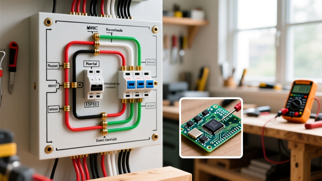
Before grabbing a multimeter, you must understand the architectural blueprint of a standard 200-amp, single-phase, 120/240V split-phase panel. The diagram typically highlights three critical zones:
- The Service Entrance & Main Disconnect: Where the utility drop (usually 4/0 AWG aluminum or 2/0 AWG copper) terminates at the main lugs or main breaker. Diagrams here help identify if the panel is a 'Main Lug' (requiring an upstream disconnect) or 'Main Breaker' configuration.
- The Hot Bus Bars (A and B Legs): Alternating 120V phases. A wiring diagram shows which physical breaker slots correspond to Phase A and Phase B. This is crucial for balancing loads and diagnosing 240V appliance failures.
- The Neutral and Ground Infrastructure: In a main service panel, the neutral and ground bars are bonded. In subpanels, they must remain strictly isolated. Diagrams reveal the main bonding jumper location and the routing of the Grounding Electrode Conductor (GEC).
Tracing the Path of Least Resistance
When a fault occurs, current seeks the path of least resistance back to the source. By overlaying your physical findings onto the panel's wiring diagram, you can determine if a fault is occurring on the branch circuit, the feeder, or the service drop itself. For instance, if a voltage drop is measured at a receptacle, the diagram helps you trace the specific breaker, identify if it is part of a daisy-chained MWBC, and locate the exact bus bar phase it connects to.
Common Wiring Failures and Diagram-Based Solutions
Below is a diagnostic matrix mapping common residential symptoms to their underlying schematic-level causes and the precise steps required to verify and fix them.
| Symptom Reported | Diagram Clue / Suspect Area | Diagnostic Action | Resolution & NEC Standard |
|---|---|---|---|
| AFCI Breaker trips randomly | Shared neutral on MWBC or crossed neutrals between adjacent single-pole breakers. | Clamp meter around both hot and neutral at the breaker. If net current ≠ 0mA, a neutral leak exists. | Separate neutrals onto dedicated bar lugs; ensure MWBC uses a 2-pole breaker with handle tie (NEC 210.4). |
| Flickering lights on one leg | Loose connection on Phase A or B main bus stab, or degraded utility transformer tap. | Measure voltage Line-to-Neutral on both legs under load. A variance >3V indicates a loose lug. | Torque main lugs to manufacturer spec (e.g., 40-50 in-lbs for 2/0 Cu) per NEC 110.14(D). |
| Melted neutral wire insulation | Two hot legs of an MWBC landed on the SAME phase bus bar instead of opposite phases. | Check breaker slots against the panel schematic. If both are on Phase A, neutral carries the sum (not difference) of currents. | Move one breaker to the opposite phase slot so the 240V potential cancels neutral current. |
| Subpanel chassis is 'hot' (tingle) | Floating neutral or missing equipment grounding conductor (EGC) in subpanel diagram. | Measure voltage from subpanel ground bar to a known earth ground (e.g., water pipe). | Isolate neutral bar from ground bar in subpanel; run dedicated 4-wire feeder (NEC 250.32). |
Deep Dive: Troubleshooting Multi-Wire Branch Circuits (MWBC)
The MWBC is the most frequently misunderstood topology in residential electrical panel wiring. It utilizes two hot wires (one from Phase A, one from Phase B) sharing a single neutral wire. When wired correctly according to the schematic, the 180-degree phase shift means the neutral only carries the imbalance of the two loads. If Circuit A draws 10A and Circuit B draws 8A, the neutral carries only 2A.
The 'Same Phase' Catastrophe
If a previous DIYer or careless electrician moves one of the MWBC breakers to a slot on the same phase (e.g., moving from slot 1 to slot 3 in a standard Square D HOMELINE panel), both hot wires are now 120V in-phase. The neutral will now carry the sum of the loads (10A + 8A = 18A). If the neutral is #14 AWG (rated for 15A), it will overheat, melt, and potentially ignite the wall cavity, all while the 15A breakers remain completely un-tripped because neither individual hot wire exceeded 15A.
Pro Tip: Always use a 2-pole breaker or a factory-approved handle tie for MWBCs. This not only ensures the breakers land on opposite phases (based on the panel's internal bus stab layout) but also satisfies the NEC requirement for simultaneous disconnect, protecting anyone working downstream.
Advanced Diagnostics: AFCI and GFCI Nuisance Tripping
With the 2023 and 2026 NEC cycles mandating AFCI protection in nearly all living spaces and GFCI protection in kitchens, bathrooms, and outdoors, nuisance tripping is the number one service call. Wiring diagrams are essential here because combination-type AFCI breakers (like the Eaton BRCAF120) monitor both parallel and series arcs, and they are highly sensitive to downstream wiring errors.
- Verify the Pigtail Connection: The diagram for an AFCI/GFCI breaker always shows a white coiled pigtail that must terminate directly to the panel's neutral bar. If this pigtail is landed on the ground bar (a common error in main panels where the bars are bonded), the breaker's internal logic board will detect a ground fault and trip immediately upon reset.
- Trace Downstream Neutral Mix-ups: If a homeowner replaced a standard receptacle with a GFCI receptacle downstream of an AFCI breaker, and accidentally connected the load-side neutral to a non-GFCI circuit's neutral, the AFCI breaker will see current returning on the wrong path and trip. Use the panel schematic to identify all breakers feeding that specific room, turn them all off, and perform a continuity test between the suspect neutral and ground to find the cross-wired junction box.
Essential Diagnostic Tools for 2026
To effectively troubleshoot using wiring diagrams, you need precision instruments. Guesswork leads to misdiagnosis and repeated service calls.
- Fluke 87V Industrial Multimeter (~$450): Essential for true-RMS voltage measurements and continuity testing. Its low-impedance mode (LoZ) prevents ghost voltage readings when tracing open neutrals on a schematic.
- FLIR E54 Thermal Imaging Camera (~$1,600): Allows you to scan the panel under load. A loose terminal lug or a failing bus stab will illuminate as a hot spot (often 20°F to 40°F above ambient) long before it causes a catastrophic failure.
- Klein Tools CL800 Clamp Meter (~$130): Crucial for measuring neutral current on MWBCs without breaking the circuit.
- CDI 1002MFRMH Torque Screwdriver (~$180): NEC 110.14(D) mandates that all terminations be torqued to manufacturer specifications. For standard 15A/20A breakers, this is typically 20-25 in-lbs. Hand-tightening is no longer code-compliant or safe.
Safety Protocols and Code Compliance
Working inside a live residential panel exposes you to arc flash hazards and lethal shock. Even with the main breaker turned OFF, the service entrance lugs remain energized by the utility grid. Always wear appropriate PPE, including voltage-rated gloves and safety glasses, as outlined by OSHA's Electrical Safety Standards.
Furthermore, when modifying residential electrical panel wiring based on your diagram findings, ensure you are using listed and classified components. Mixing breaker brands (e.g., placing a Siemens QT breaker into an Eaton BR panel) violates NEC 110.3(B) and voids the panel's UL listing. Always consult the panel's internal wiring diagram label, which explicitly lists the approved, tested breaker models for that specific enclosure. For comprehensive load center specifications and approved accessory diagrams, refer directly to manufacturer resources like the Eaton Residential Loadcenters catalog.
Frequently Asked Questions
Can I use a generic wiring diagram for any 200A panel?
No. While the basic split-phase principles are identical, the physical bus bar stab layout (which slots correspond to Phase A vs. Phase B) varies drastically between Square D, Eaton, Siemens, and GE panels. Using the wrong diagram for MWBC placement can result in overloading a shared neutral.
Why does my panel diagram show a bond screw, but my subpanel doesn't have one?
The main service disconnect requires a main bonding jumper (screw or strap) to tie the neutral and ground together, establishing the zero-reference point for the system. Subpanels must keep neutral and ground isolated to prevent neutral return current from traveling on the equipment grounding conductors, which can cause chassis electrification.
How do I trace a circuit if the panel diagram label is missing?
If the factory schematic is faded or missing, you must map the panel manually. Use a non-contact voltage tester and a circuit tracer (like the Klein Tools ET910) to identify the hot leg. To determine the phase, measure the voltage between the suspect breaker and a known Phase A breaker. If you read 240V, it's Phase B; if you read 0V, it's Phase A.