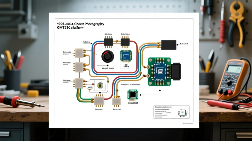

Decoding the GMT330 Electrical Architecture
The Chevy S10, specifically the second-generation GMT330 platform (1998–2004), remains a cornerstone of the DIY truck and restoration community. However, locating an accurate, easy-to-read wiring diagram for Chevy S10 models of this era is only half the battle. General Motors transitioned heavily into the Class 2 Serial Data network during these years, meaning a simple break in an 18-gauge communication wire can disable your instrument cluster, ABS module, or PCM. Furthermore, 20-year-old PVC insulation and high-resistance grounds plague these trucks. This guide bypasses the vague factory service manual fluff and delivers actionable pinouts, failure modes, and modern repair strategies for the S10 electrical system.
Master Wiring Diagram Reference Matrix
Before probing any circuit with a multimeter, cross-reference the critical load circuits below. These wire colors and gauges apply to the 1998–2004 4.3L V6 and 2.2L I4 S10 configurations.
| Circuit Function | Primary Wire Color | SAE Gauge | Fuse Rating | Common GMT330 Failure Mode |
|---|---|---|---|---|
| Headlight Feed (MFS) | Yellow | 14 AWG | 20A | Multifunction switch melting / high resistance |
| Fuel Pump Supply | Gray | 12 AWG | 20A | Harness chafing at the bed crossmember |
| Starter Solenoid (S) | Purple | 10 AWG | N/A (Ign) | Voltage drop at neutral safety switch |
| Class 2 Serial Data | Dark Green / White Stripe | 18 AWG | N/A | Corrosion at OBD-II DLC Pin 2 |
| Alternator Sense (CS144) | Red | 12 AWG | 30A (Megafuse) | Under-hood junction block corrosion |
| PCM Ignition 1 (Run) | Pink | 16 AWG | 15A | Ignition switch internal contact pitting |
The Notorious Multifunction Switch (MFS) Meltdown
If your S10's turn signals are acting erratically, or your headlights are flickering and you smell melting plastic near the steering column, you are experiencing the classic GMT330 MFS failure. On these trucks, the full amperage of the headlight circuit (often exceeding 15 amps combined for low beams and DRLs) is routed directly through the turn signal switch contacts. Over time, resistance builds, heat accumulates, and the plastic harness pigtail melts.
The Bosch Relay Bypass Fix
Rather than replacing the $85 multifunction switch only to have it melt again in two years, perform a headlight relay bypass. This removes the heavy load from the column switch, using it only as a low-amperage trigger.
- Disconnect the Battery: Follow OSHA electrical safety guidelines by isolating the negative terminal and waiting 10 minutes for the PCM capacitors to discharge.
- Identify the Trigger: Locate the Yellow 14 AWG headlight feed wire at the base of the steering column.
- Install the Relay: Wire a standard 4-pin 12V automotive relay (e.g., Bosch 0332014150). Connect the Yellow wire to Pin 86 (Coil +). Ground Pin 85 (Coil -) to a clean chassis bolt.
- Run New Power: Run a new 12 AWG fused (20A) wire directly from the under-hood fuse block's BAT+ stud to Relay Pin 30.
- Feed the Headlights: Connect Relay Pin 87 to the factory headlight harness downstream of the MFS.
Pro-Tip: Never solder under-hood or under-dash harness repairs where vibration is present. Solder creates a rigid joint that will fatigue and snap. Use adhesive-lined marine heat shrink crimp connectors to maintain flexibility and moisture resistance.
OBD-II Data Link Connector (DLC) Pinout
When your check engine light illuminates, or you are swapping in a custom PCM for an LS engine conversion, understanding the 16-pin DLC is mandatory. The S10 uses GM's Class 2 architecture, not the modern CAN-bus found in 2008+ vehicles.
- Pin 2 (Class 2 Data): Dark Green/White. The main communication bus. If this shorts to ground, the truck will start but the scanner will not link, and the cluster will die.
- Pin 4 (Chassis Ground): Black. Must have less than 0.05V drop to the battery negative.
- Pin 5 (Signal Ground): Black/White. Dedicated ground for PCM sensor returns. Do not combine with Pin 4.
- Pin 16 (Battery Positive): Orange. Constant 12V, fused at 15A (CIGAR/ECM-B fuse in the dash block).
Fuel Pump Circuit & The Oil Pressure Myth
A massive point of confusion for S10 owners is the fuel pump prime. Many DIYers mistakenly search for an 'inertia cutoff switch' (a feature standard on Ford Rangers of the same era). The Chevy S10 does not have an inertia switch.
Instead, the S10 uses a dual-path fuel pump circuit:
- Primary Path: When the key hits 'ON', the PCM grounds the fuel pump relay coil for exactly 2 seconds to prime the system. If the PCM sees RPM reference signals (cranking/running), it keeps the relay grounded.
- Backup Path: If the fuel pump relay fails, current is routed through the oil pressure sender switch. Once oil pressure reaches roughly 4 PSI, the mechanical switch closes, powering the fuel pump directly to prevent the engine from stalling due to a $15 relay failure.
Diagnostic Edge Case: If your S10 cranks but takes 10+ seconds to start, and you hear the fuel pump kick on after the engine begins firing, your primary fuel pump relay is dead, and the truck is running solely on the oil pressure backup circuit. Check the F/PMP relay in the under-hood fuse block immediately.
Alternator Upgrades: CS130 vs. CS144 Wiring
Early GMT330 S10s came with the infamous CS130 alternator, known for poor internal voltage regulator cooling and bearing failures. Upgrading to the larger CS144 (124-amp) is a common modification, but the 4-pin pigtail requires specific wiring to prevent overcharging or dashboard 'Battery' light illumination.
| CS Alternator Pin | Function | Wiring Requirement |
|---|---|---|
| S (Sense) | Reads actual battery voltage | Must be wired directly to the BAT+ terminal on the alternator or the main junction block. Never ground it. |
| L (Lamp) | Turns on dash indicator | Wired to the PCM or ignition-switched 12V through a 100-ohm resistor or standard LED bulb to prevent overvoltage spikes. |
| I (Ignition) | Wakes up the regulator | Switched 12V from the ignition 'Run' circuit (Pink wire). |
| F (Field) | PCM PWM Control | Used on newer models; leave unconnected on standard CS144 standalone swaps. |
Wire Repair Standards and Best Practices
When modifying or repairing your S10 harness, adherence to industry standards is critical for fire prevention and signal integrity. According to SAE International (Standard J1128), wire gauge selection must account for both current draw and ambient under-hood temperatures. A 14 AWG wire rated for 20 amps in a cool cabin environment will suffer severe voltage drop and potential insulation melting when routed near the S10's exhaust manifolds. Always step up one gauge (e.g., to 12 AWG) for under-hood runs exceeding 4 feet.
Furthermore, consult the NHTSA Recall Database for your specific VIN before modifying the airbag (SIR) system wiring. The S10's yellow-jacketed SIR harnesses carry low-voltage, high-sensitivity signals; using standard test lights on these circuits can inadvertently deploy the steering wheel airbag.
Frequently Asked Questions
Where is the main ground distribution block on the S10?
The primary ground distribution block is located on the left side of the engine block, near the cylinder head. Additionally, a critical ground strap connects the passenger side cylinder head to the firewall, and another from the back of the block to the chassis frame. If your headlights dim when using the power windows, clean the firewall ground strap first.
Can I use a modern Bluetooth OBD2 scanner on a 1998 S10?
Yes, but with caveats. Because the 1998-2004 S10 uses GM Class 2 data (ISO 9141-2 / J1850 VPW protocols) rather than modern CAN-bus, cheap ELM327 clones often fail to read ABS or SRS modules. Invest in a high-quality adapter like the OBDLink EX or Vgate iCar Pro, which natively support GM VPW protocols for full-module diagnostics.
Why does my S10 blow the ECM-B fuse immediately upon turning the key?
The ECM-B fuse powers the fuel pump relay coil, the PCM keep-alive memory, and the OBD-II Port Pin 16. A dead short here is almost always caused by a melted OBD-II port (where Pin 16 shorts to Pin 4 ground) due to a dropped cigarette lighter charger, or a chafed fuel pump harness where it passes over the rear axle crossmember.