
Understanding the ANSI/TIA-568 Standard in Modern Networks
In modern network infrastructure, referencing an accurate wiring diagram for ethernet cable is no longer just about establishing a basic data link; it is a critical safety and performance requirement. With the widespread adoption of 10GBASE-T and IEEE 802.3bt Type 4 Power over Ethernet (PoE) delivering up to 100W over copper, improper termination can lead to severe signal degradation, alien crosstalk (AXT), or even thermal damage to RJ45 connectors. According to the ANSI/TIA-568.2-D standard, which governs balanced twisted-pair telecommunications cabling, strict adherence to pinout color codes and physical untwisting limits is mandatory to maintain category bandwidth ratings.
Whether you are deploying Cat5e for basic IoT sensors, Cat6a for high-density enterprise Wi-Fi 7 access points, or Cat8 for 25G/40G data center top-of-rack connections, the fundamental 8-position, 8-contact (8P8C) wiring diagram remains consistent. However, the physical tolerances and shielding requirements have become significantly more stringent.
The Core Wiring Diagram for Ethernet Cable: T568A vs. T568B
The TIA/EIA standard defines two primary wiring schemes: T568A and T568B. Both are fully compliant and offer identical electrical performance, but they differ in the arrangement of the orange and green pairs. In the United States, T568B is the de facto commercial standard, while T568A is often mandated in government contracts and residential new-builds to maintain backward compatibility with older USOC telephone wiring.
| Pin | T568A Color Code | T568B Color Code | Signal / PoE Function (1000BASE-T & 802.3bt) |
|---|---|---|---|
| 1 | White/Green | White/Orange | TX+ / Data & PoE (+) |
| 2 | Green | Orange | TX- / Data & PoE (-) |
| 3 | White/Orange | White/Green | RX+ / Data & PoE (+) |
| 4 | Blue | Blue | BI_DA+ / Data & PoE (+) |
| 5 | White/Blue | White/Blue | BI_DA- / Data & PoE (-) |
| 6 | Orange | Green | RX- / Data & PoE (-) |
| 7 | White/Brown | White/Brown | BI_DB+ / PoE (+) |
| 8 | Brown | Brown | BI_DB- / PoE (-) |
Expert Insight: Never mix T568A on one end and T568B on the other unless you are intentionally building a legacy crossover cable. Doing so on a modern network will result in a 'split pair' fault, which a basic continuity tester might miss, but which will cause massive crosstalk and fail a Fluke Networks certification test.
Straight-Through vs. Crossover: Do You Still Need Both?
Historically, network technicians had to memorize the crossover wiring diagram for ethernet cable to connect like-devices (e.g., switch-to-switch or PC-to-PC). A crossover cable uses T568A on one end and T568B on the other, swapping the transmit and receive pairs.
Today, virtually all gigabit and multi-gigabit network interfaces feature Auto-MDIX (Automatic Medium-Dependent Interface Crossover). This technology automatically detects the cable type and electronically swaps the TX and RX pairs internally. Therefore, straight-through cables (T568B to T568B) are universally recommended for all modern patch cords and permanent links. Crossover cables are now largely relegated to legacy 10/100 Mbps equipment or specific lab environments.
High-Power PoE (IEEE 802.3bt) and Pinout Safety
The introduction of Type 3 (60W) and Type 4 (90W-100W) PoE has transformed the wiring diagram from a data map into a power delivery schematic. Unlike older PoE standards that only utilized pins 1, 2, 3, and 6, 802.3bt pushes DC current across all four twisted pairs simultaneously.
- Thermal Hazards: If a pin is poorly terminated or a wire strand is clipped during the flush-cut phase, the resistance on that specific contact increases. Under a 90W load, this localized resistance can cause the RJ45 contact to exceed 80°C, potentially melting the polycarbonate plug housing.
- Gauge Requirements: Always use solid 23 AWG copper for permanent links and stranded 24 AWG or 26 AWG for patch cords. Avoid Copper Clad Aluminum (CCA) entirely, as its higher resistance and brittleness make it a severe fire hazard under high-wattage PoE.
Precision Termination: Step-by-Step Protocol
Achieving a passing grade on a BICSI-certified installation requires strict adherence to physical handling limits. Follow this protocol for terminating Cat6 and Cat6a cables:
- Strip the Jacket: Use a dedicated stripping tool (like the Klein Tools VDV226-110) to remove exactly 1.5 inches (38mm) of the outer PVC or LSZH jacket. Do not score the inner copper conductors.
- Manage the Drain Wire (Shielded Cable Only): If using F/UTP or S/FTP cable, fold the bare copper drain wire back over the jacket. This must eventually make contact with the metal zinc-alloy housing of a shielded RJ45 plug to dissipate electrostatic discharge (ESD).
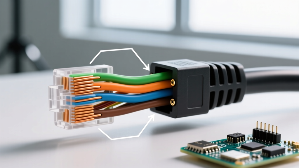
- Untwist the Pairs: Untwist the pairs only as far as necessary to arrange them into the T568A or T568B sequence. Critical Limit: Do not untwist more than 0.5 inches (13mm) for Cat6, and no more than 0.25 inches (6mm) for Cat6a. Exceeding this limit destroys the electromagnetic cancellation of the twist, causing Near-End Crosstalk (NEXT) failures.
- Align and Flatten: Pinch the base of the wires and slide them back and forth to flatten them into a single, tight row. Ensure the color sequence matches your chosen standard perfectly.
- Flush Cut: Using precision flush cutters, trim the wires exactly 0.5 inches from the base of the jacket. The cut must be perfectly perpendicular (90 degrees) so all eight copper ends hit the back of the RJ45 plug simultaneously.
- Insert and Crimp: Slide the plug over the wires, verifying the jacket extends fully into the rear strain-relief crimp of the plug. Use a pass-through crimping tool to ensure the conductors are fully seated before the blade trims the excess.
Handling Shielded Cables (Cat6a and Cat8)
When deploying 10GBASE-T or 25GBASE-T, unshielded cables are highly susceptible to Alien Crosstalk (AXT) when bundled tightly in cable trays. Shielded cables (F/UTP, U/FTP, S/FTP) mitigate this but require specialized termination techniques. The wiring diagram for ethernet cable in a shielded environment demands that the foil shielding and drain wire are continuously bonded from the equipment chassis, through the patch panel, and into the shielded RJ45 connector. If the drain wire is left floating or trimmed away, the shield acts as an antenna, actually amplifying high-frequency interference rather than blocking it. For further reading on structured cabling best practices, refer to this comprehensive T568A vs T568B structural guide.
Common Failure Modes and Diagnostics
Even with the correct wiring diagram, field terminations frequently fail certification due to the following edge cases:
1. Split Pairs
A split pair occurs when a technician wires pin 3 and pin 6 using two different twisted pairs (e.g., White/Orange and White/Blue) instead of the same pair (White/Green and Green). A cheap $20 continuity tester will show a green light because the circuit is complete, but a certifier will fail the link immediately due to massive NEXT. Always verify that pins 3 and 6 share the exact same base color and stripe pattern.
2. Open Circuits on PoE Pins
If pins 4, 5, 7, or 8 are poorly crimped, gigabit data might still negotiate if the cable is forced into a 100Mbps fallback (which only uses 1, 2, 3, 6), but high-wattage PoE will fail to initialize or will trigger the PSE (Power Sourcing Equipment) overcurrent protection, shutting down the switch port entirely.
3. Excessive Return Loss
Return loss measures signal reflections caused by impedance mismatches. This is almost always caused by untwisting the pairs too far back, or by using mismatched components (e.g., terminating a solid 23 AWG permanent link cable with an RJ45 plug designed for stranded 24 AWG patch cable). Always match the plug geometry to the conductor type.
Final Verification
Never assume a manually crimped cable is viable for production traffic based solely on link lights. In 2026, with multi-gigabit Wi-Fi 7 access points drawing 40W+ and requiring flawless 10Gbps backhaul, every terminated link should be verified with a Wiremapper at minimum, and ideally a full Channel Certifier like the Fluke Networks DS2-800-M, to ensure the physical wiring diagram translates into verified, error-free bandwidth.