
Decoding the Ignition Switch Circuit Architecture
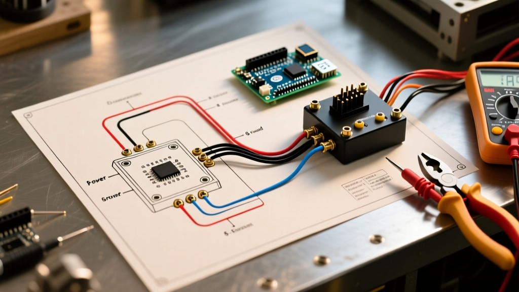
When a vehicle fails to crank, or accessories remain dead when the key is turned, the ignition switch is the primary suspect. However, blindly swapping parts without consulting a wiring diagram for ignition switch circuits is a hallmark of amateur diagnostics. The ignition switch is not merely an on/off toggle; it is a complex, multi-position rotary distributor that routes battery current to distinct vehicular subsystems based on the key cylinder's physical detents.
To troubleshoot effectively in 2026, you must understand how to map the physical switch terminals to the schematic symbols on your factory service manual (FSM) diagram. Modern vehicles integrate these circuits with Body Control Modules (BCMs) and immobilizer networks, making precise voltage verification more critical than ever.
CRITICAL SAFETY WARNING: Before probing any steering column wiring, disconnect the negative battery terminal and wait at least 15 minutes. The ignition switch is routed directly adjacent to the Supplemental Restraint System (SRS) airbag clock spring. Accidentally back-probing an SRS wire can trigger deployment. Always refer to NHTSA safety guidelines regarding steering column component servicing.
Standard Terminal Designations on a 5-Position Diagram
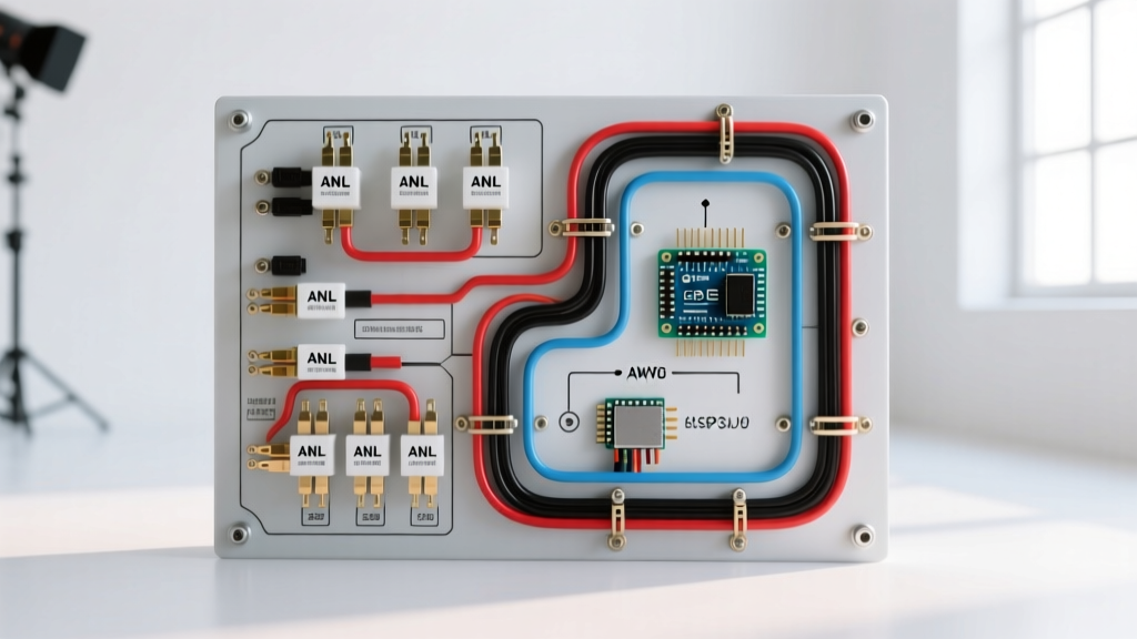
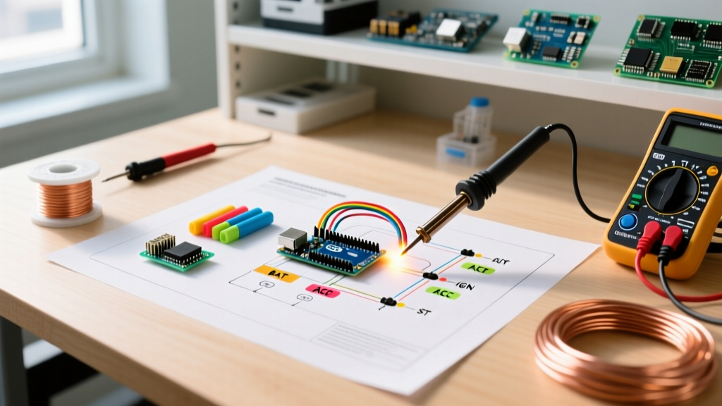
Most automotive wiring diagrams for ignition switches utilize a standardized alphanumeric nomenclature to identify the switch's internal wiper contacts. While wire colors vary wildly between manufacturers (e.g., GM typically uses heavy-gauge red for battery feeds, while Ford may use yellow with a black trace), the terminal functions remain universal.
| Terminal ID | Function | Typical Wire Gauge | Active Key Positions | Expected Voltage |
|---|---|---|---|---|
| BAT / B+ | Main Battery Feed | 10 - 12 AWG | All Positions (Constant) | 12.2V - 12.6V |
| ACC | Accessory Circuit | 14 - 16 AWG | ACC, RUN | 12.2V (in ACC/RUN) |
| IGN / IG | Ignition / ECU Power | 12 - 14 AWG | RUN, START | 12.2V (in RUN/START) |
| ST / S | Starter Solenoid Signal | 14 - 16 AWG | START Only | 12.2V (in START) |
| ILLUM | Key Cylinder Illumination | 18 - 20 AWG | Headlights ON | 12.2V (Variable w/ PWM) |
Step-by-Step Troubleshooting Using the Diagram
A wiring diagram is only useful if you know how to test the nodes it represents. The most reliable method for diagnosing a failing ignition switch is voltage drop testing under load, rather than simple continuity testing.
Phase 1: Verifying the BAT (Battery) Feed
Locate the BAT terminal on the diagram. This wire connects directly to the main fuse block or battery positive post via a heavy-gauge cable (often protected by a 40A to 60A maxi-fuse).
- Set your Digital Multimeter (DMM) to DC Volts.
- Connect the black probe to a known good chassis ground.
- Back-probe the BAT wire at the switch connector with the red probe.
- Diagnostic Criteria: You must read full battery voltage (minimum 12.2V). If you read 0V, your issue is upstream (blown main fuse or corroded battery cable). If you read 10.5V, you have severe upstream resistance.
Phase 2: Testing the ACC and IGN Circuits
Turn the key to the RUN position. According to the diagram, the internal wiper should now bridge the BAT contact to both the ACC and IGN terminals.
- The Voltage Drop Test: Move your red probe from the BAT wire to the IGN wire. The difference in voltage between the BAT terminal and the IGN terminal is the voltage drop across the switch's internal contacts.
- Expert Threshold: A healthy switch exhibits a voltage drop of less than 0.1V. If your DMM reads a drop of 0.5V or higher, the internal copper wipers are pitted, carbonized, or suffering from weak detent spring tension. The switch must be replaced.
Phase 3: Diagnosing the ST (Start) Signal Path
The START circuit is where most misdiagnoses occur. The diagram will show the ST wire leaving the switch, but it rarely goes straight to the starter solenoid. It typically routes through a Neutral Safety Switch (NSS) on automatic transmissions, or a Clutch Pedal Position (CPP) switch on manuals, and often passes through an anti-theft relay.
If you have 12.2V at the ST terminal on the back of the ignition switch when held in the START position, but the starter does not engage, use the wiring diagram to trace the next node. Back-probe the output side of the NSS. If voltage is present at the switch but absent at the NSS output, the transmission range sensor is misaligned or failed.
Common Failure Modes and Edge Cases
When consulting a wiring diagram for ignition switch diagnostics, keep these real-world edge cases in mind:
1. Melted Molex Connector Pigtails
The BAT terminal carries the entire electrical load of the vehicle's RUN circuits. Over time, micro-arcing and high resistance cause the plastic Molex connector housing to melt, pushing the female terminal out of alignment. Fix: Do not just replace the switch. Inspect the pigtail connector. As of 2026, OEM replacement pigtails (like the ACDelco PT115 or Motorcraft WPT-1243) cost between $14 and $28 and must be soldered and sealed with marine-grade heat shrink.
2. Passlock and Immobilizer Interference
In many GM and Ford vehicles, the ignition switch housing contains a Passlock sensor or PATS transceiver ring. If the wiring diagram shows a 3-wire or 4-wire data bus exiting the switch housing alongside the power circuits, you are dealing with an immobilizer. If the security light flashes on the dash, the switch may be mechanically turning, but the BCM is intentionally disabling the ST circuit or cutting fuel injector pulses.
3. Mechanical Detent Wear vs. Electrical Failure
Sometimes the electrical switch is perfectly fine, but the plastic actuator rack between the key cylinder and the switch has worn down. You can verify this by removing the switch from the column and manually rotating the switch actuator with a flathead screwdriver while monitoring your DMM. If the switch clicks cleanly and passes the voltage drop test manually, your wiring diagram is irrelevant—the fault is mechanical wear in the steering column housing.
Essential Tools and Real-World Costs
Professional troubleshooting requires precision tools. Guessing with a cheap test light can lead to misdiagnosing a high-resistance fault.
| Tool / Component | Recommended Spec / Model | 2026 Est. Price Range | Purpose |
|---|---|---|---|
| Digital Multimeter | Fluke 87V MAX or Klein Tools MM700 | $250 - $420 | Accurate millivolt drop testing |
| Wire Piercing Probes | Fluke TP81 or Lisle 39570 | $25 - $45 | Back-probing sealed connectors safely |
| OEM Ignition Switch | ACDelco D1461G (GM) / Motorcraft SW-6356 (Ford) | $35 - $95 | Direct replacement (Avoid cheap aftermarket) |
| Connector Pigtail | Dealer-specific harness pigtail | $14 - $28 | Repairing melted BAT terminal housings |
For advanced diagnostics, technicians often rely on continuity testing to verify broken wires inside the steering column loom. Following the rigorous testing protocols outlined by Fluke Corporation, ensure the circuit is completely de-energized before switching your DMM to the continuity/ohms setting to prevent blowing the multimeter's internal fuse.
Expert FAQ
Can I bypass the ignition switch with jumper wires to start the car?
While you can theoretically jump the BAT and ST terminals to engage the starter, this bypasses the neutral safety switch and the immobilizer. Furthermore, jumping the heavy BAT terminal to the low-gauge IGN or ACC wires will instantly melt the harness and blow the main fuse panel. Never use jumper wires on a multi-pole ignition switch connector.
Why does my radio turn off when I crank the engine?
This is by design. Reviewing the wiring diagram for the ignition switch reveals that the ACC (Accessory) circuit is intentionally severed during the START position. This sheds non-essential electrical loads to ensure maximum cold-cranking amps (CCA) are directed to the starter motor and ECU.
My key won't turn, is it the switch or the cylinder?
The ignition switch is the electrical component bolted to the column; the ignition cylinder is the mechanical lock tumbler where the key inserts. If the key won't turn, the issue is mechanical (worn key, broken tumbler wafers, or steering column lock binding). The wiring diagram only applies once the cylinder successfully rotates the switch actuator.