
Mastering the Wiring Diagram for Motor Circuits in 2026
Whether you are commissioning a new 5HP conveyor drive or retrofitting an aging HVAC blower, interpreting a wiring diagram for motor controls is a foundational skill for any electrical professional. In 2026, with the rise of smart VFDs and IoT-integrated motor starters, the basic principles of electromechanical control remain unchanged, but the integration layers have grown more complex. A misread schematic or improperly sized termination doesn't just trip a breaker; it causes thermal runaway, insulation breakdown, and catastrophic equipment failure.
This comprehensive tutorial breaks down the anatomy of motor control diagrams, from basic Direct-On-Line (DOL) starters to advanced Variable Frequency Drives (VFDs), providing actionable torque specs, wire sizing matrices, and real-world troubleshooting frameworks.
⚠ Safety First: LOTO and Arc Flash Protocols
Before interacting with any motor control center (MCC) or starter enclosure, you must adhere to OSHA Lockout/Tagout guidelines. Verify zero energy using a CAT III or CAT IV rated multimeter (e.g., Fluke 87V). Never rely solely on a VFD's digital display to confirm the absence of voltage, as internal DC bus capacitors can retain lethal charges (up to 650V DC on 480V AC systems) for minutes after disconnect.
Decoding the Standard Wiring Diagram for Motor Circuits
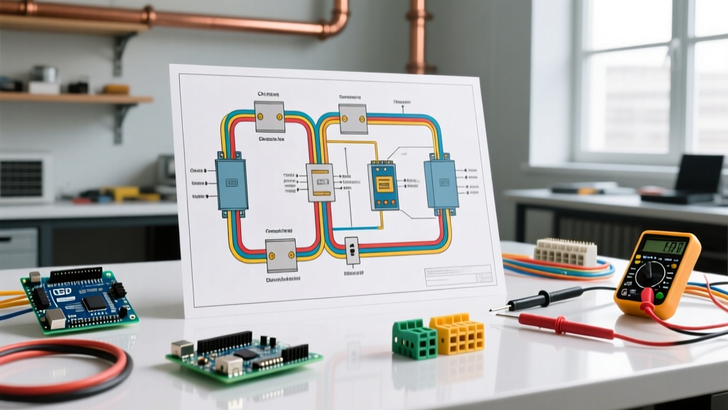
When you pull a schematic from an equipment manual, you will typically encounter one of two global standards: NEMA (predominant in North America) or IEC (common in Europe and modern global OEM equipment). Understanding the visual language of your specific wiring diagram for motor applications prevents costly cross-wiring errors.
| Feature | NEMA Schematics | IEC Functional Diagrams |
|---|---|---|
| Layout Style | Ladder logic format; power and control circuits often separated vertically. | Functional block format; components grouped by physical location or function. |
| Component Sizing | Oversized for high endurance and heavy inrush currents (e.g., NEMA Size 1). | Compact, application-specific sizing based on exact AC-3 duty cycle ratings. |
| Contact Labels | L1, L2, L3 (Line) and T1, T2, T3 (Load). | 1L1, 3L2, 5L3 (Line) and 2T1, 4T2, 6T3 (Load). |
| Typical Cost (10A) | $120 - $180 (e.g., Eaton Freedom Series) | $45 - $75 (e.g., Schneider TeSys D LC1D09) |
Direct-On-Line (DOL) Starter Wiring Walkthrough
The DOL starter is the most common electromechanical configuration for motors under 10HP. Below is a step-by-step physical wiring sequence for a standard 480V, 3-phase system using an Allen-Bradley 100-C09 contactor and a solid-state overload relay.
- Isolate and Prep: Lock out the upstream 30A disconnect. Strip 1/2 inch of insulation from your 12 AWG THHN phase wires.
- Line Termination: Land L1, L2, and L3 on the top terminals of the contactor. Critical Spec: Torque the M4 power screws to exactly 1.2 Nm (10.6 lb-in). Under-torquing causes micro-arcing; over-torquing strips the brass threading.
- Load Termination: Connect T1, T2, and T3 from the bottom of the contactor to the top of the thermal overload relay block.
- Motor Feed: Wire the bottom of the overload relay (U2, V2, W2) directly to the motor peckerhead. Ensure the motor's internal jumper links match the voltage (Star for 480V, Delta for 240V).
- Control Circuit Wiring: Pull 18 AWG control wire from a 120V step-down transformer. Route through the stop button (Normally Closed), then the start button (Normally Open), and finally to the contactor's A1 coil terminal. Tie A2 to the neutral bus.
- Seal-in Circuit: Wire a Normally Open (NO) auxiliary contact block in parallel with the start button to maintain coil energization after the operator releases the button.
Integrating a VFD: Wiring Diagram for Motor Speed Control
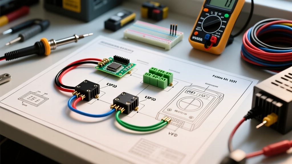
When your application requires soft starting, dynamic braking, or precise speed regulation, you transition from a DOL starter to a Variable Frequency Drive. Let's look at wiring an Allen-Bradley PowerFlex 523 (5HP, 480V) for a centrifugal pump application.
Power Wiring and Grounding
VFDs are highly sensitive to voltage spikes and high-frequency noise. Your wiring diagram for motor speed control must include proper shielding.
- Input Power (R, S, T): Connect incoming 480V 3-phase power. Do not wire a standard circuit breaker between the VFD and the motor; the VFD's internal IGBTs handle short-circuit protection.
- Output Power (U, V, W): Use symmetrical shielded VFD cable (e.g., Belden 16AWG 3-conductor with continuous corrugated aluminum armor). Terminate the shield at the VFD's integral EMC gland using a 360-degree shield clamp. Never pigtail the shield, as this creates an antenna effect that radiates EMI into nearby 4-20mA sensor loops.
- Grounding (PE): Bond the motor frame and the VFD chassis to a dedicated earth ground bus. The ground wire must be sized equal to or larger than the phase conductors per NFPA 70 (NEC) Article 250.
Control I/O: Sink vs. Source Logic
A common failure point in 2026 VFD installations is mismatching the digital input logic. The PowerFlex 523 defaults to Sink (NPN) logic. If your PLC outputs Source (PNP) 24VDC signals, the drive will not recognize the start command. You must physically move the jumper on the VFD's control board from 'SNK' to 'SRC' and adjust Parameter t046 (Digital Input Logic) from 0 to 1.
Wire Gauge Sizing and Thermal Overload Settings
Sizing conductors for motors is not as simple as using standard NEC ampacity tables for resistive loads. According to NFPA 70 National Electrical Code (NEC) Article 430, motor branch circuit conductors must be sized at 125% of the motor's Full Load Amps (FLA), while the short-circuit protection device (breaker) is sized much higher to accommodate the massive inrush current (LRA) during startup.
| Motor HP (480V 3φ) | NEC Table 430.250 FLA | Min Wire Size (THHN 75°C) | Max Inverse Time Breaker | Overload Relay Setting |
|---|---|---|---|---|
| 3 HP | 4.8 A | 14 AWG | 15 A | 5.5 A (115% FLA) |
| 7.5 HP | 11 A | 12 AWG | 30 A | 12.6 A (115% FLA) |
| 15 HP | 21 A | 10 AWG | 50 A | 24.1 A (115% FLA) |
| 30 HP | 40 A | 6 AWG | 100 A | 46.0 A (115% FLA) |
Pro Tip: If your motor is installed in an environment where the ambient temperature exceeds 40°C (104°F), you must derate the thermal overload setting or upgrade the wire insulation to XHHW-2 (rated for 90°C) to prevent nuisance tripping and insulation degradation.
Troubleshooting Common Motor Wiring Failures
Even with a perfect wiring diagram for motor setups, field conditions introduce variables that cause failures. Here is how to diagnose the three most common catastrophic issues using industry-standard testing protocols endorsed by the Schneider Electric Motor Control Standards and independent testing labs.
1. Single-Phasing (Phase Loss)
The Failure: One phase of the 3-phase supply drops out (often due to a blown fuse or a loose utility connection). The motor continues to run on the remaining two phases, but the current spikes to 173% of the FLA. Standard bimetallic overloads may not trip fast enough, melting the stator windings.
The Fix: Upgrade to a solid-state electronic overload relay (e.g., ABB TA25DU) with built-in differential phase-loss detection. Test the circuit by intentionally pulling one control fuse and verifying the relay trips within 3 seconds.
2. Voltage Drop and Thermal Runaway
The Failure: Long cable runs (over 150 feet) cause a voltage drop at the motor terminals. Because P = V x I, as voltage drops, the motor draws proportionally more current to maintain mechanical torque, leading to overheating.
The Fix: Measure voltage at the MCC and then at the motor peckerhead under full mechanical load. If the drop exceeds 3% (14.4V on a 480V system), you must upsize the conductors. Do not rely on open-circuit voltage readings; the drop only manifests under load.
3. VFD Reflected Wave (dV/dt) Insulation Failure
The Failure: The high-speed PWM pulses from a VFD create standing waves on long motor cables. The peak voltage at the motor terminals can reach 2x the DC bus voltage (nearly 1300V on a 480V system), punching through standard motor winding insulation.
The Fix: If the cable run exceeds 50 feet, install a dV/dt filter at the VFD output, or ensure the motor is specifically rated as an 'Inverter Duty' motor with Class H (180°C) insulation and a minimum dielectric withstand of 1600V peak.
"The most common mistake we see in the field is technicians treating a VFD output like standard 60Hz sine wave power. A wiring diagram for motor speed control isn't just about connecting point A to point B; it's about managing high-frequency impedance and protecting the motor's dielectric envelope from PWM voltage spikes."
— Senior Commissioning Engineer, Industrial Automation Sector
Final Commissioning Checklist
Before energizing any newly wired motor circuit, run through this final verification matrix:
- Megger Test: Use a 1000V insulation tester (e.g., Megger MIT485) phase-to-ground. Acceptable reading: >100 Megohms for new installations. Anything below 2 Megohms requires winding bake-out or replacement.
- Rotation Check: Bump the motor (momentarily energize) to verify shaft rotation matches the driven equipment requirements. Swapping any two phase legs (L1 and L2) will reverse a 3-phase motor's direction.
- Amp Draw Verification: Clamp a true-RMS ammeter around each phase individually. The readings should be balanced within 2% of each other and not exceed the nameplate FLA.
Mastering the interpretation and physical execution of a wiring diagram for motor controls separates standard electricians from elite industrial technicians. By respecting torque specifications, adhering to NEC Article 430 sizing rules, and understanding the high-frequency realities of modern VFDs, you ensure maximum uptime and equipment longevity.