
Understanding a wiring diagram for HVAC equipment is the dividing line between a guesswork parts-swapper and a true diagnostic technician. Modern central air conditioning and heat pump split systems rely on a complex interplay between high-voltage power delivery and low-voltage logic control. Whether you are upgrading to a smart thermostat like the Ecobee SmartThermostat (typically around $250) or troubleshooting a failed compressor contactor, the manufacturer's schematic is your ultimate roadmap.
In this comprehensive reference guide, we will dissect the standard wiring diagram for HVAC split systems, tracing the electrical path from the main service panel down to the micro-switches inside the thermostat. We will also cover exact multimeter diagnostics, specific component failure modes, and critical safety codes mandated by the National Electrical Code (NEC).
The Two Halves of the HVAC Electrical System
Every residential split system wiring diagram is divided into two distinct electrical domains: the line-voltage power circuit and the low-voltage control circuit. Confusing these two is the most common cause of blown control board fuses and catastrophic component failure.
| Characteristic | Line Voltage Circuit | Low Voltage Control Circuit |
|---|---|---|
| Standard Voltage | 208/230V AC (Single Phase) | 24V AC |
| Primary Function | Powering compressor, blower, and fan motors | Logic signaling, thermostat communication, relay switching |
| Standard Wire Gauge | 10 AWG to 6 AWG (Copper/Aluminum) | 18 AWG (Solid Copper, 18/5 or 18/8) |
| Overcurrent Protection | 30A to 60A Double-Pole Breaker | 3A ATO Blade Fuse (on control board) |
| Typical Wire Colors | Black, Red, White, Bare/Green | Red, White, Yellow, Green, Blue/Black |
Decoding the Low-Voltage Control Circuit
The low-voltage side of the wiring diagram for HVAC systems originates at the control board's 24VAC transformer. This transformer steps down the 230V line voltage to a safe 24VAC, which is then routed to the thermostat and various safety switches (high-pressure, low-pressure, and float switches).
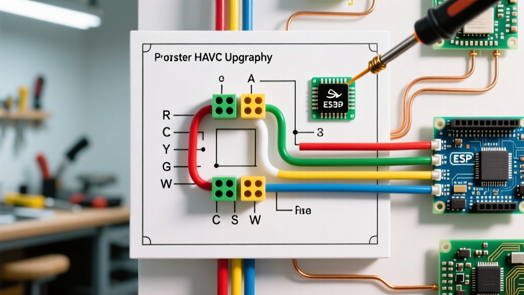
Standard Thermostat Wire Color Codes
While the U.S. Department of Energy notes that wire colors are not strictly mandated by code, the industry standard for 18/5 thermostat wire is nearly universal:
- R (Red): 24VAC Hot. This is the primary power source from the transformer.
- C (Blue/Black): 24VAC Common. Completes the circuit for the control board and smart thermostats requiring continuous power.
- W (White): Heat Call. Routes 24VAC to the heating relay or gas valve.
- Y (Yellow): Cooling Call. Routes 24VAC to the outdoor condenser contactor coil.
- G (Green): Fan Call. Routes 24VAC to the indoor blower motor relay.
The 3-Amp Fuse Vulnerability
On almost all modern air handler control boards (such as the Honeywell ST9120U), you will find a 3-amp automotive-style blade fuse protecting the 24VAC transformer. If the Y wire chafes against a copper refrigerant line or the outdoor contactor coil shorts out, this fuse blows instantly. When reading the wiring diagram, always trace the 'C' or 'R' path through this fuse before assuming a transformer failure.
Tracing the High-Voltage Condenser Circuit
The high-voltage side of the diagram details how 230V power reaches the outdoor unit. Power leaves the main panel via a 30A double-pole breaker, travels through 10 AWG UF-B or THWN wire in conduit, and enters the outdoor disconnect box.
The Contactor and Dual Run Capacitor
From the disconnect, L1 and L2 enter the condenser control box and terminate on the line side of the Definite Purpose Contactor (e.g., a Packard C340B 40-Amp contactor, costing roughly $18). When the thermostat calls for cooling, the 24VAC low-voltage signal energizes the contactor's magnetic coil. This pulls the contacts down, allowing 230V to flow to the compressor and the condenser fan motor.
Simultaneously, the wiring diagram will show a dual run capacitor (commonly a 45/5 MFD Titan Pro, around $12). The capacitor provides the necessary phase shift to generate starting torque for the compressor (HERM terminal) and the fan motor (FAN terminal), while the C terminal connects to the common line voltage.
Sequence of Operation: A Cooling Call
To truly master the wiring diagram for HVAC systems, you must understand the chronological sequence of electrical events during a standard cooling call:
- Thermostat Closure: The internal temperature rises above the setpoint. The thermostat closes the circuit between R and Y, and R and G.
- Blower Engagement: 24VAC travels down the G wire, energizing the indoor blower relay. The indoor fan begins circulating air.
- Contactor Energization: 24VAC travels down the Y wire, passing through the outdoor high-pressure and low-pressure safety switches, and reaches the contactor coil. The coil generates a magnetic field, pulling the high-voltage contacts closed.
- Compressor Start: 230V flows through the contactor to the compressor run windings and the HERM terminal on the capacitor. The compressor starts pumping refrigerant.
- Condenser Fan Start: 230V simultaneously flows to the fan motor and the FAN terminal on the capacitor, pulling heat from the condenser coils.
Advanced Multimeter Diagnostics & Failure Modes
Reading the schematic allows you to isolate faults logically. Below is a diagnostic matrix based on real-world failure modes encountered in split systems.
| Symptom | Electrical Test Point | Expected Value | Actual Reading & Failure Point |
|---|---|---|---|
| Thermostat blank, no AC | Control Board R to C | 24V AC ± 10% | 0V AC: Blown 3A fuse or failed 40VA transformer. |
| Indoor fan runs, outdoor unit dead | Contactor Coil (A1 to A2) | 24V AC | 0V AC: Tripped float switch, broken Y wire, or open pressure switch. |
| Contactor pulls in, compressor hums and trips breaker | Dual Capacitor (C to HERM) | 45 µF ± 6% | < 38 µF: Degraded capacitor dielectric. Replace immediately. |
| Contactor chatters or buzzes loudly | Contactor Coil Resistance | 10 to 30 Ohms | > 100 Ohms or OL: Failing coil or debris on magnetic armature. |
Pro Tip: Never test a run capacitor with a multimeter without first discharging it. Use a 20,000-ohm, 5-watt resistor across the terminals for 5 seconds. Failing to do so can destroy your multimeter's internal circuitry or cause a severe arc flash.
Code Compliance and Safety Mandates
When modifying or repairing HVAC wiring, strict adherence to electrical codes is non-negotiable. According to NFPA 70 (National Electrical Code), specifically Article 440, air-conditioning and refrigerating equipment must have a properly rated disconnecting means within sight of the motor-compressor. Furthermore, the branch circuit conductors must be sized at 125% of the motor-compressor rated load current (RLA).
Additionally, the ENERGY STAR heating and cooling guidelines emphasize that improper wiring and poor electrical connections increase electrical resistance, leading to voltage drops that can reduce system efficiency by up to 5% and drastically shorten compressor lifespan. Always torque high-voltage lug connections to the manufacturer's specified inch-pound rating (typically 35-45 in-lbs for standard 10 AWG lugs) to prevent thermal expansion and arcing.
Summary
A wiring diagram for HVAC equipment is not just a suggestion; it is the exact electrical blueprint of the system. By understanding the separation of 24VAC logic and 230VAC power, recognizing standard component symbols, and applying systematic multimeter testing based on the schematic, you can diagnose complex faults safely and efficiently. Always verify power is disconnected at the main breaker and the outdoor disconnect before opening any condenser control panels.