
Decoding the Wiring Diagram for RV Motor Applications
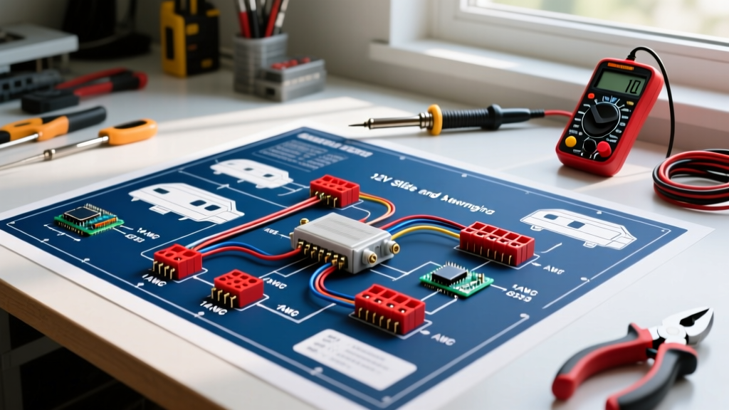
When you unroll a factory wiring diagram for RV electrical systems, the sheer density of lines, nodes, and color codes can be overwhelming. Unlike residential wiring, which relies on standardized 120V/240V AC alternating current, recreational vehicles operate on a complex dual-voltage architecture. The most critical and frequently modified circuits involve 12V DC high-torque motors—specifically slide-out mechanisms, motorized awnings, and leveling jacks.
Understanding the wiring diagram for RV motor circuits is not just about connecting positive to negative; it is about managing high amperage, mitigating voltage drop over long chassis runs, and ensuring proper polarity reversal. In this comprehensive motor wiring tutorial, we will dissect the 12V DC reversing motor circuits used by industry giants like Lippert Components (LCI) and Carefree, providing you with the exact wire gauges, breaker sizes, and relay logic required for a bulletproof installation.
The Golden Rule of RV Motor Wiring: A 12V DC motor does not care about the color of the wire; it only cares about electron flow direction. Reversing the polarity across the two motor terminals instantly reverses the motor's rotation. The entire purpose of an RV slide-out wiring diagram is to safely manage this polarity swap without creating a dead short.
The Core Architecture: 12V DC Reversing Motor Logic
Most 12V RV slide-out motors, such as the ubiquitous Lippert 158925 through-wall motor, feature only two wire terminals. To extend the slide, current flows from Terminal A to Terminal B. To retract it, current must flow from Terminal B to Terminal A. Factory wiring diagrams achieve this using one of two methods:
- DPDT (Double Pole Double Throw) Momentary Switch: A specialized 6-terminal rocker switch that physically crosses the positive and negative feeds when toggled up or down, returning to a center-off position when released.
- Dual Bosch-Style Relay Harness: Two 5-pin 40A automotive relays wired in an H-bridge configuration, triggered by a low-amperage SPDT (Single Pole Double Throw) switch. This is common in motorized awnings and newer hydraulic pump solenoids.
Step 1: Power Source and Overcurrent Protection
Never wire an RV motor directly to the battery without overcurrent protection. According to the NFPA 1192 Standard for Recreational Vehicles, all ungrounded conductors must be protected within 18 inches of the power source. For a standard 20A slide motor, install a Blue Sea Systems 4238 30A Thermal Circuit Breaker (Type III, manual reset) directly on the positive battery post or main distribution busbar. This protects the wire from melting in the event of a seized motor or mechanical bind.
Step 2: The DPDT Reversing Switch Harness
If your wiring diagram for RV slide controls utilizes a 6-pin DPDT switch, the wiring cross-over is the most common point of DIY failure. The switch has two center terminals (Motor Leads), two top terminals (12V Positive In), and two bottom terminals (Ground In). You must install jumper wires diagonally across the top and bottom terminals to create the polarity-reversing 'X' pattern. When the switch is pressed 'Out', the left center terminal receives 12V+ and the right receives Ground. Pressing 'In' swaps these feeds.
Step 3: Motor Terminals and Chassis Grounding
Run your two 10 AWG motor leads from the switch to the motor. Unlike AC motors, 12V DC motors do not require a dedicated ground wire if the motor casing is bolted directly to a clean, unpainted metal chassis frame. However, because RV frames are prone to rust and flex, best practice dictates running a dedicated 10 AWG ground wire from the motor casing back to the main negative busbar, ensuring a zero-resistance return path.
RV Motor Wire Gauge and Breaker Sizing Matrix
Undersized wiring is the leading cause of premature RV motor failure. The table below provides exact specifications for common RV motor applications, assuming a maximum one-way wire run of 25 feet (50 feet total circuit length).
| Motor Application | Typical Model | Max Amp Draw | Wire Gauge (25ft Run) | Breaker Size |
|---|---|---|---|---|
| Slide-Out (Through-Wall) | Lippert 158925 | 22A | 10 AWG Stranded | 30A Thermal |
| Motorized Awning | Carefree Fiesta | 14A | 12 AWG Stranded | 20A Thermal |
| Hydraulic Pump Motor | Lippert Ground Control | 50A (Peak) | 4 AWG Stranded | 60A ANL Fuse |
| HVAC Blower (120V AC) | Dometic Penguin II | 3.5A | 14 AWG Solid (AC) | 15A AC Breaker |
| 12V Water Pump | Shurflo 4008 | 10A | 12 AWG Stranded | 15A Thermal |
Critical Failure Modes: Why RV Motors Burn Out
When troubleshooting an RV motor that hums but won't turn, or one that trips the breaker instantly, DIYers often blame the motor itself. In reality, 80% of these failures stem from poor wiring practices that starve the motor of voltage or introduce excessive resistance. Consult the Lippert Support Portal for diagnostic flowcharts, but keep these three physical failure modes in mind:
1. The Voltage Drop Math That Saves Your Motor
DC motors are highly sensitive to voltage drop. If a Lippert slide motor requires 11.5V to generate enough torque to push a 3,000 lb slide room, but your wiring drops the voltage to 9.8V, the motor will stall. When a DC motor stalls, it stops generating back-EMF and pulls locked-rotor amperage (LRA), which can exceed 60A, instantly melting 12 AWG wire.
The Math: 10 AWG copper wire has a resistance of roughly 1.018 ohms per 1,000 feet. For a 25-foot run (50 feet round trip), the resistance is 0.0509 ohms. At a 20A draw, the voltage drop is V = I × R (20 × 0.0509 = 1.01 Volts). This leaves 11.4V at the motor (assuming a 12.4V battery), which is perfectly safe. If you mistakenly use 14 AWG wire, the drop increases to 2.5V, stalling the motor.
2. Corroded Butt Splices and High Resistance
Standard vinyl-insulated crimp connectors are not waterproof. In the underbelly of an RV, moisture wicks into unsealed crimps, creating copper oxide. This oxidation acts as a resistor, generating intense heat. Always use heat-shrink marine-grade butt splices (like Ancor or Blue Sea) with an internal ring of adhesive meltable sealant.
3. Mechanical Bind Masquerading as Electrical Faults
Before rewiring a motor that keeps tripping a 30A breaker, manually crank the slide-out using the manual override tool. If the mechanical linkage is dry, bent, or obstructed by debris, the motor will over-amp regardless of how perfect your wiring diagram for RV applications is. Lubricate the rack and pinion gears with white lithium grease before condemning the electrical circuit.
2026 Upgrades: Best Practices for RV Motor Wiring
As RVs have grown heavier and more complex, the electrical demands on 12V systems have increased. If you are rewiring an older rig or upgrading a factory installation, implement these modern standards:
- Marine-Grade Tinned Copper: Bare copper wire turns black and brittle from vibration and moisture over a few seasons. Upgrade to Ancor marine-grade tinned wire (approx. $1.80/ft in 2026). The tin coating prevents oxidation and ensures flexible strands that resist vibration fatigue.
- Adel Clamps for Routing: Never zip-tie heavy 10 AWG motor wires directly to sharp chassis edges or hot exhaust components. Use rubber-cushioned Adel P-clamps secured with stainless steel hardware to route wires safely along the frame rails.
- Dielectric Grease on Terminals: Apply a dab of dielectric tune-up grease to the motor spade terminals before attaching the female disconnects. This displaces moisture and prevents the galvanic corrosion that frequently seizes RV slide motors to their mounting brackets.
Frequently Asked Questions
Can I use a standard automotive 40A relay instead of a DPDT switch for my RV slide?
Yes, but you must wire two 5-pin Bosch-style relays in an H-bridge (polarity reversing) configuration. This requires a low-amperage SPDT trigger switch. While this reduces the heavy current traveling to the dashboard switch, it introduces two potential points of relay failure. For high-draw slide motors, a heavy-duty marine DPDT rocker switch rated for 35A is generally more reliable and easier to troubleshoot.
Why does my awning motor run slower when extending than when retracting?
This is rarely an electrical wiring issue. Extending an awning requires the motor to fight gravity and unroll the fabric against the tension of the gas struts or torsion springs. Retracting is assisted by that same tension. However, if the speed difference is drastic, check your battery bank voltage; a weak house battery will sag heavily under the asymmetric load of extension.
For further reading on DC circuit protection and wire sizing, refer to the Blue Sea Systems Circuit Protection guidelines, which provide excellent visual charts for marine and RV DC environments.